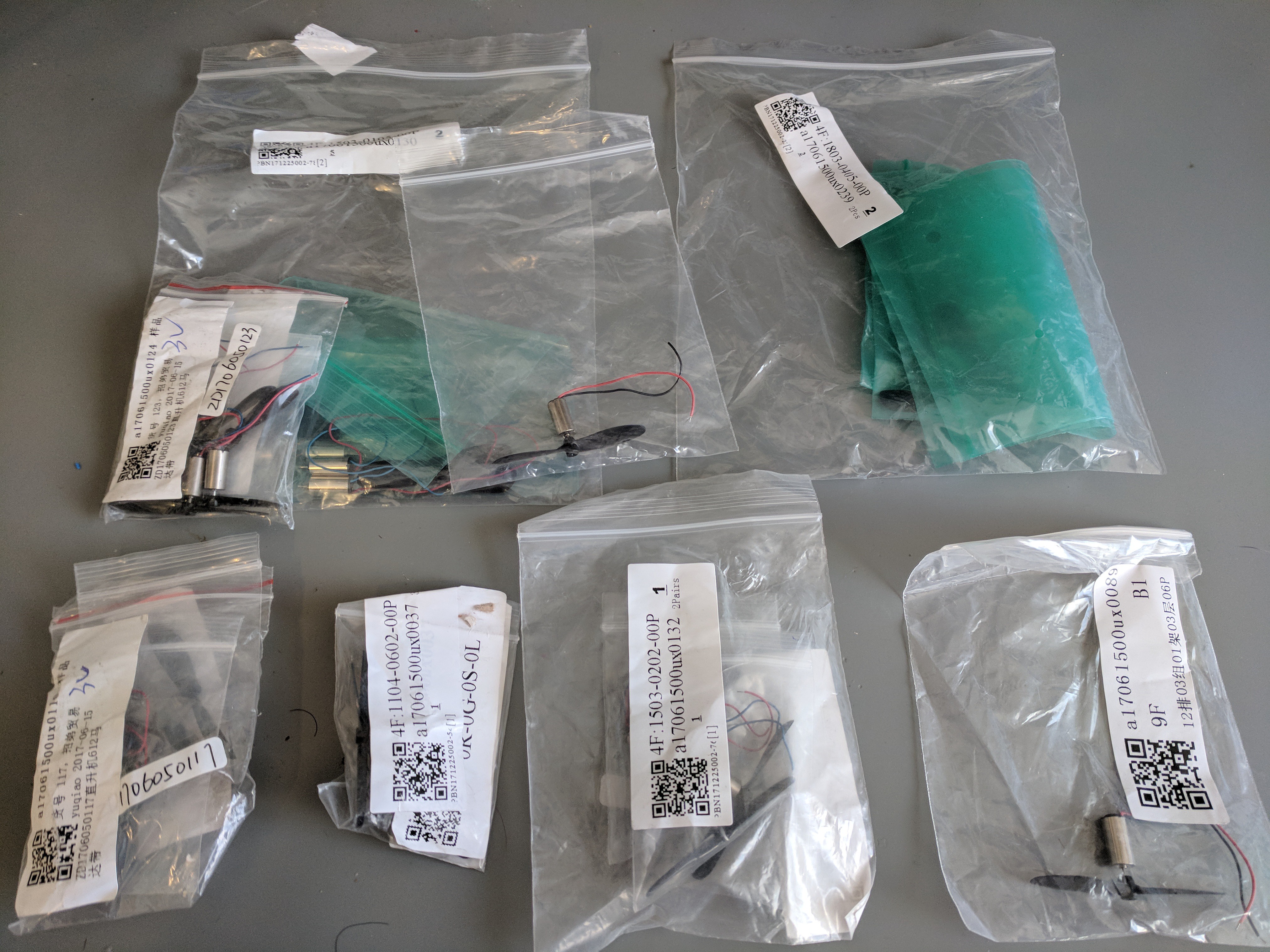
My flight test showed me that my motors didn't have enough lift/ draw enough current/ rotate fast enough. I ordered several motors to test from Uxcell ranging from 13,000 rpms to 40,000 rpms.

All the motors I bought have rpm ratings + voltage, but no kV rating.
Motor kV (the rpm constant, not kilovolts) is the relationship between rpm and generated back emf (force). It's defined as the number of revolutions per minute (rpm) that the motor will turn when 1V is applied to the motor with no load. So rpms/ volt.
A low kV (more winds, thinner wire) will have higher volts/ less amps/ higher torque so it can swing a larger propeller.
A high kV (less winds, thicker wire) will have low volts/ higher amps/ lower torque for swinging a smaller propeller.

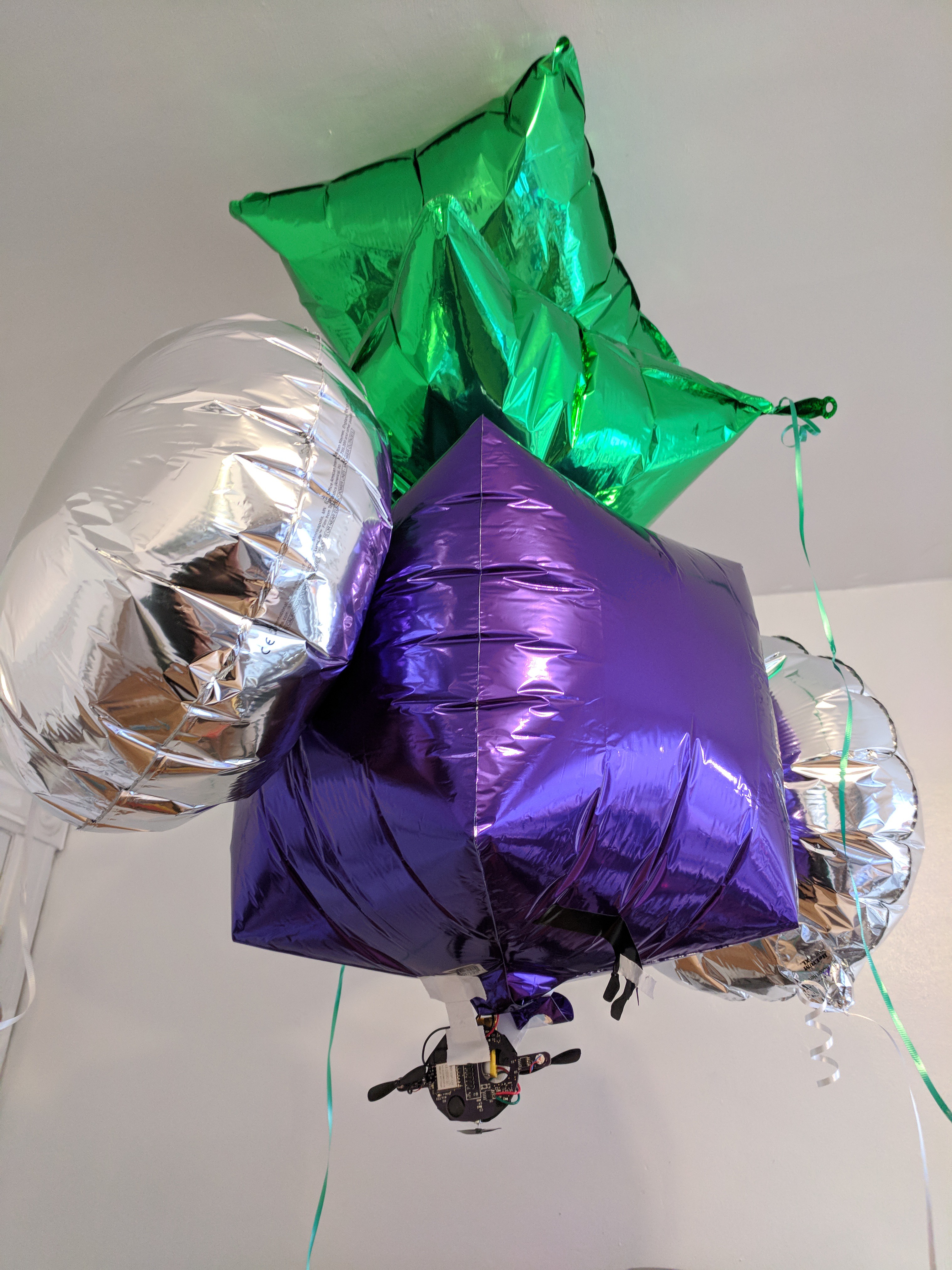
The blimp is working a lot better. The motors are just not fast enough, nor are the propellers moving enough air to make enough of a difference. I put a 500 mA battery on it which is why now there are 5 balloons needed to hold it up :/ (I am afraid to weigh the gondola now).
 Sophi Kravitz
Discussions
Become a Hackaday.io Member
Create an account to leave a comment. Already have an account? Log In.
Another thing to consider is the positioning of the lift motor. Where is it pulling the air from? The body of the blimp is mostly blocking the draft from above, so it is pulling the air from the sides. This is like building a drone with the lift propeller directly underneath the body. I don't really know how much this might impact the lift, but a possible test for the amount of lift produced for an obstructed v. an un-obstructed prop would be to hang the unit underneath a spring scale, such as is used for measuring the weight of fish, or baggage or whatever. Try it with an un-obstructed view of the air above and then try it by blocking as much air as the blimp blocks.
Are you sure? yes | no
I think I'll keep the 3 motors split on 2 chips until I work out the control scheme :) but hey! an extra high current output for LEDs is quite interesting ...
Are you sure? yes | no
Lasers, Sophi, lasers. :)
Are you sure? yes | no
I don't have any motors with kV ratings. I think they are designed for little drones though! There's a power problem. The motor drivers LA6585 are good for a maximum of 700 mA, but there is no way even 200 mA is getting there. I suspect that the voltage regulator I've chosen has too high of a drop and is not allowing enough voltage (measured is 2.9 V) to power the drivers/ motors etc.
Are you sure? yes | no
Do you need a regulator for the motors? The datasheet for the LA6585 says it can use a 14V supply - can't it just use the battery voltage directly?
Are you sure? yes | no
No, I don't need a regulator for the motors, but I need it for the ESP. I have a couple of things going on which are hard to troubleshoot when I know my power system is flaky. ESP is not getting enough power- it can go down to 3.0V but I consistently measure 2.9V...
But that's a good idea for testing, I could route the battery direct to the driver and see if that helps. Thanks!
Note: I have some other motors here from an unknown source that are 10x as fast +draw 10x current. I'm not having luck sourcing them though.
Are you sure? yes | no
Also, do you have a source for good helium? The "consumer tanks" are diluted with air and produce less lift.
Are you sure? yes | no
yeah, helium comes from the dollar store, it's plenty lift-y :)
Are you sure? yes | no
I had a look at the schematic you posted in the files section. I hope you don't mind a few unsolicited suggestions :-) I don't have the full picture, so take them with a grain of salt.
D1 looks like a problem - going from Vbatt to the regulator. What is its purpose? It will definitely cause a voltage drop, especially at high currents. If I'm reading it right, your motor current is being drawn through the diode, too? That would most likely be an issue.
I would also not power the motors through the regulator. Let them see the full battery voltage.
The motor drivers are interesting - from the datasheet, they appear to be designed for brushless fan motors and to be driven from hall-effect sensors. Using them for brushed motors is a nice hack. The output saturation voltages on the datasheet concern me, though. The output L sat. voltage is 0.45 max, while the H sat. voltage is 1.2 max. Together, the output drivers can eat 1.65 of your motor drive voltage (half your power!) when you are drawing 200mA. At higher currents, this will be even worse. If you need this much current or more, I'd suggest a different driver.
On the plus side, I don't see any reason from the datasheet that the drivers can't be run from a higher voltage than the ESP. At some point, the ESP outputs wouldn't be high enough to activate the driver, but with a single-cell power supply, you're probably not in danger of that. It's a quick experiment to run them from the full voltage, but it doesn't really address the output saturation voltage issue.
Oh, one more test is just connecting the motors directly to the battery, just with wire, no controller, PCB, etc. How much thrust do you get then?
Are you sure? yes | no
@Ted Yapo I appreciate the suggestions! I'm a little stuck right now tbh.
-Motors connected directly to battery get much more power
-I loved the fan driver hack too, and it is really easy to use. I chose it based on needing 70mA (tested with a toy blimp I purchased). Now that I have tested a bunch of motors, it is more like 2-300mA.
-I took the saturation voltage spec to mean that it will turn ON at L-0.25 and H-0.95 (and drawing the maximum current). Do you mean that I should be using a driver with a lower saturation to conserve all the voltage to power the motors?
Are you sure? yes | no
Yes, the output saturation is the voltage drop across the output transistors at the specified current. The datasheet has 1.2V typical and 1.65V max at 200mA (you add the H and L saturations since you have an H-side transistor saturating on one side of the motor and an L-side transistor saturating on the other). You can verify/measure these voltages with a meter, although it might help to replace the motor with a resistor for the test. 18 ohms/1W would draw 200mA at 3.6V, or you could parallel a bunch of 1/4W resistors as a test load.
The part is specified from 2-14V, but I suspect it's really targeted at 12V fans. At a 12V supply, the 1.2V typical saturation wastes 10% of the power. At a 3.3V supply, it's 36%. Worst-case 1.65V saturation means 50% wasted in the driver output transistors.
If you need 200mA or more at these supply voltages, you need beefier drivers with much lower Vsat.
And the diode and regulator just get in the way. The motor drivers should use Vbatt directly.
Are you sure? yes | no
The good people at Sparkfun, Adafruit, etc are using TB6612FNG's for example.
https://cdn-shop.adafruit.com/product-files/1944/TB6612FNG+datasheet.pdf
these are MOSFET-output drivers with 0.21V max total (L+H) saturation at 300mA. Much better.
They're duals, though, so you lose the nice 1:1 driver/motor thing, but maybe you can find a comparable single driver.
Are you sure? yes | no
HA. I'm looking at a TB6552 (also dual) - it has 0.3V at 200mA, 1.2V at 800mA. I like the tiny QFN, but the TB6612 has 0.5Vsat at 1A (but uses a SSOP24 package). I wonder if I could use the extra motor output for LEDs?
Are you sure? yes | no
@Sophi Kravitz Sure, you could drive LEDs from them. My suggestion would be to use only one output terminal for the LED driving, since you don't need (or want) to reverse "direction" on the LEDs!
I guess for a hack, you could also parallel both drivers on a dual chip for more efficiency driving the motor. Just be sure to parallel the inputs, too, so they don't fight and burn each other out.
Are you sure? yes | no
Are these motors/props designed for little drones? If so, you'd think they would produce good thrust, assuming they get enough power, I guess.
Are you sure? yes | no
What was it before? I guess less kV means also you'd have to use bigger props? So I'd say more rpm? tough choice, no idea, looks like 8 experiments to me..
Are you sure? yes | no