-
Hello World
07/06/2019 at 17:40 • 0 commentsI'm so excited that Blue Stamp Engineering is using this design for their engineering summer camp in NYC.
This is how to program the ESP8266 on the blimp PCB (note that the joystick uses an Adafruit Feather ESP32):
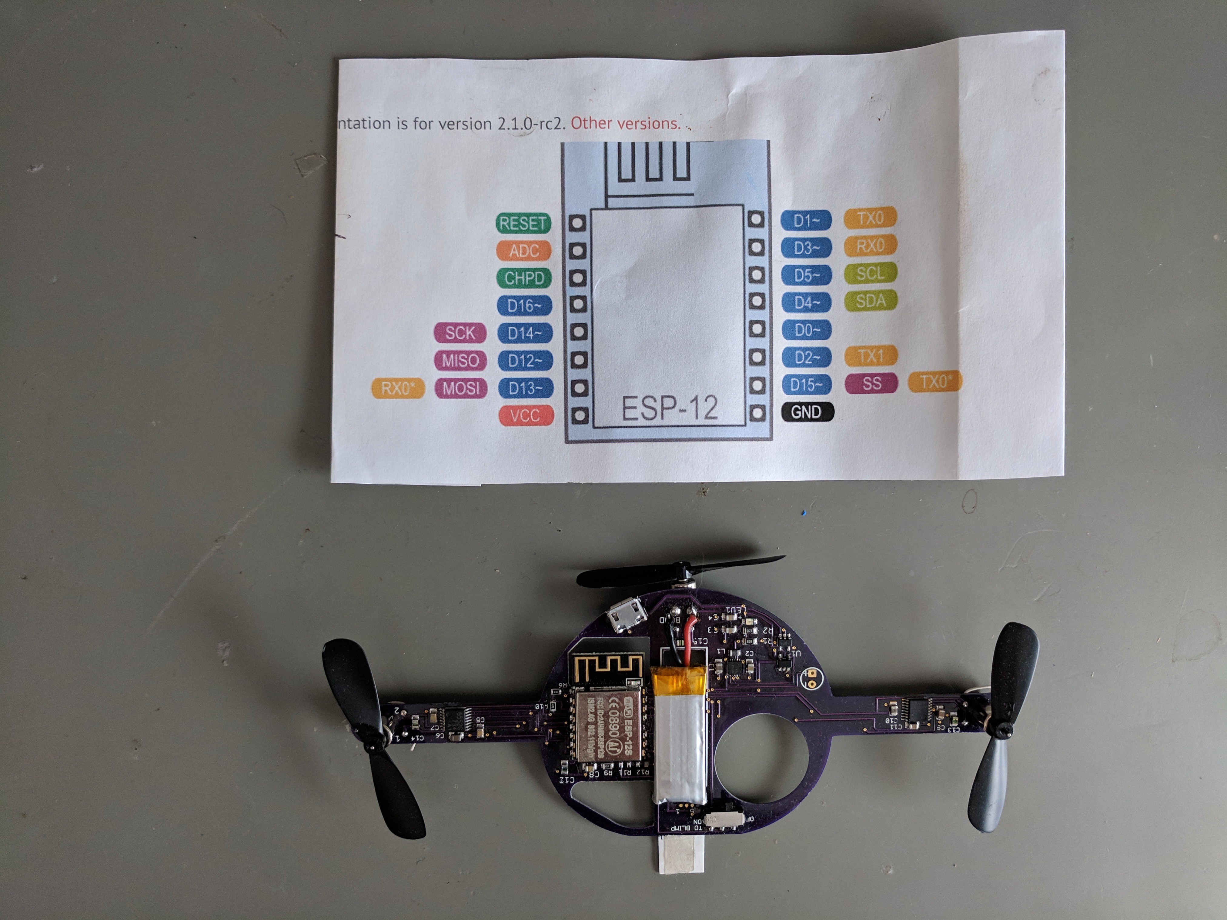
Shown here is the pinout for the ESP8266. To program it, the process is to hold D0 low, while hitting reset. D0 stays low while programming. I use a tag-connect cable PN TC2030-FTDI-TTL-232R to program the ESP8266.
![]()
Adafruit builds the programming circuit into their ESP8266 Feather board with a latching circuit (transistor). Their Huzzah board has two switches that go to Reset and D0 which you manually toggle in order to program.
These examples are excellent, and useful. However, the blimp has weight constraints so there is no room for switches or transistor circuits.
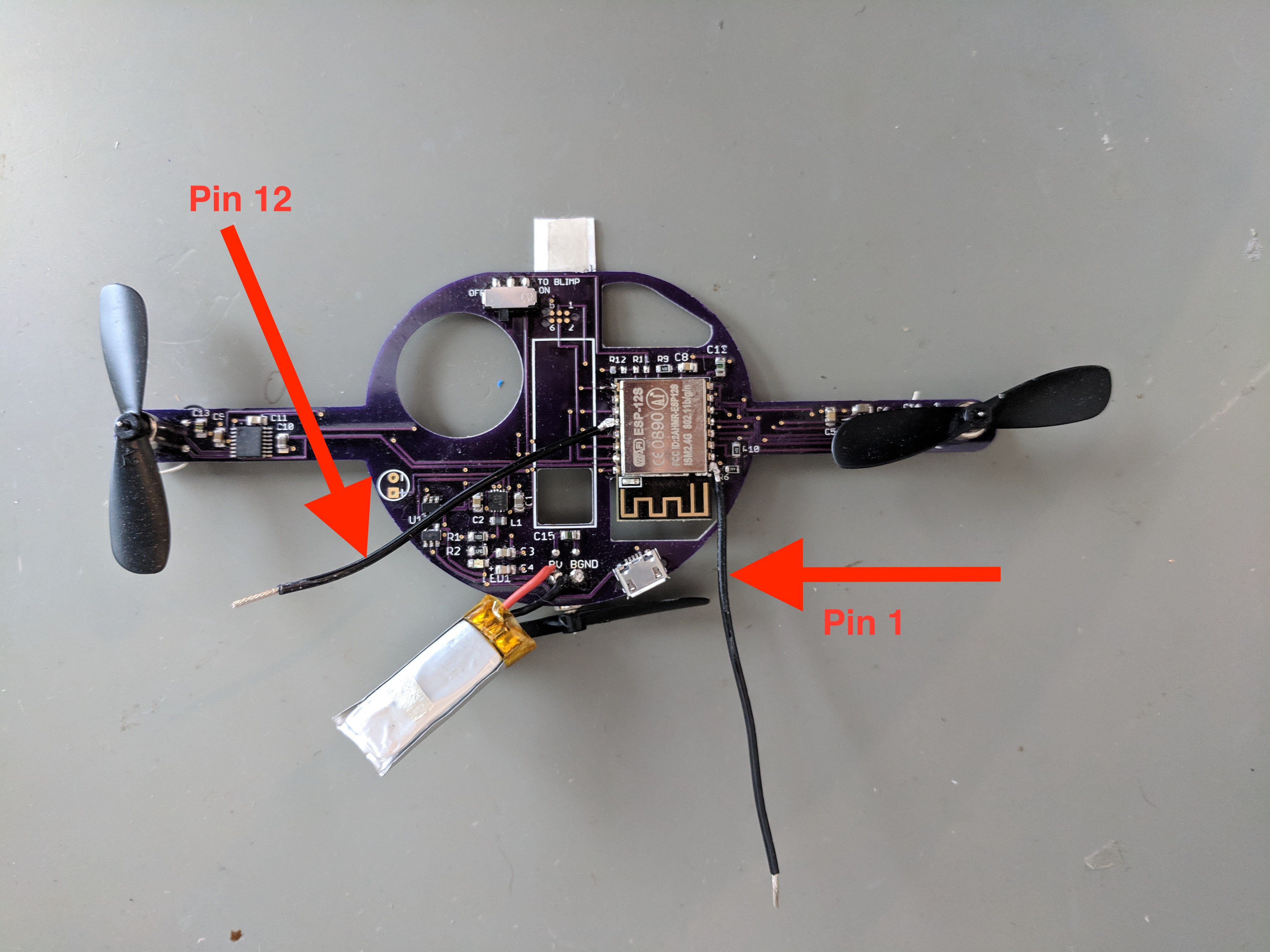
To program the board, I solder temporary wires onto the reset pin (pin1), and D0 (pin 12).
![]()
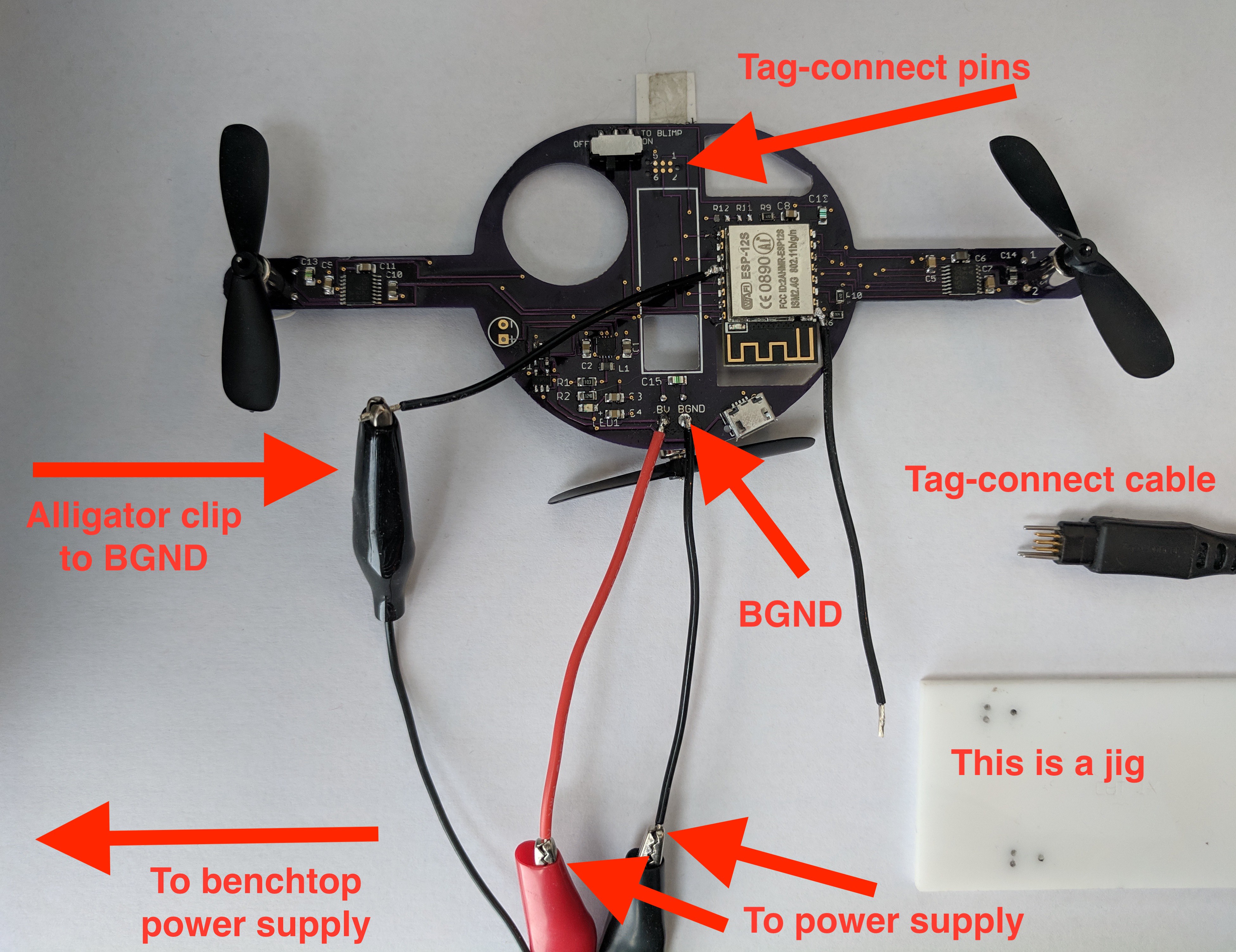
It also helps to have an extra ground wire dangling from somewhere- you can use an alligator clip from BGND to D0. Sometimes I desolder the battery and use the benchtop power supply to power the board (sometimes called the target) while programming.
![]()
There's a lot going on in the above image. This is how to connect the board:
- Benchtop power supply to anywhere between 3.4 and 4.2 V is connected to BV and BGND (B stands for battery).
- Alligator clip from BGND to D0.
- Tag-connect cable from USB on computer to tag-connect pins on board.
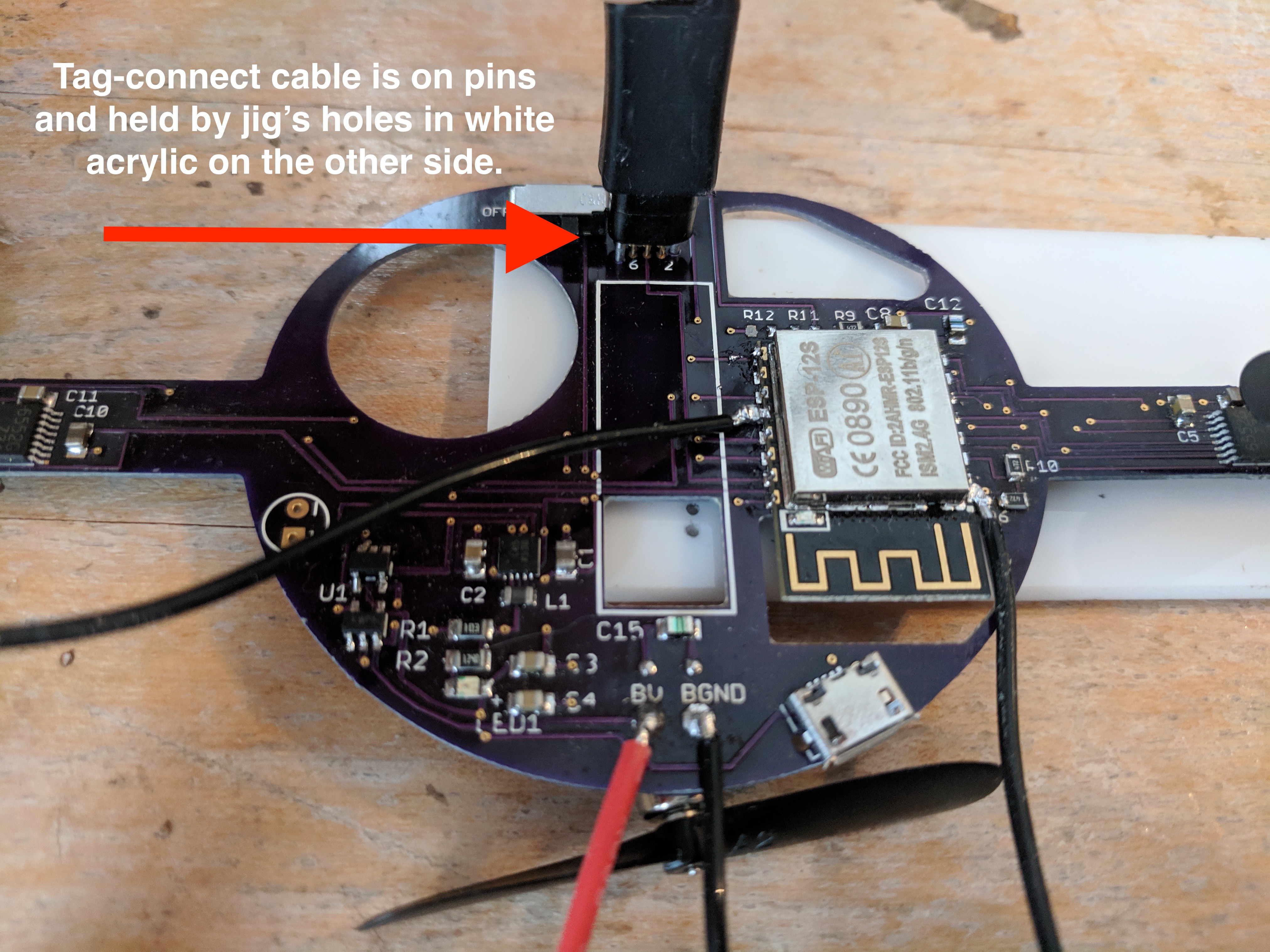
On the image below, I'll show you how the tag-connect jig works. You don't need a jig at all, but the holes in the white acrylic that line up with the tag-connect holes works quite nicely. A second person to hold the cable works quite nicely too ;)
![]()
Now that you're connected, here are the programming steps.
- Attach D0 to GND (alligator cable)
- Touch reset to ground. The black wire on pin 1 should be long enough to touch either the alligator cable or GND somewhere else. There is only one GND on the board (no separated GND planes).
When you touch reset, you should see the blue light on the ESP8266 blink. If you do not see a blue light, make sure that you've turned the switch located at the top of the board on.
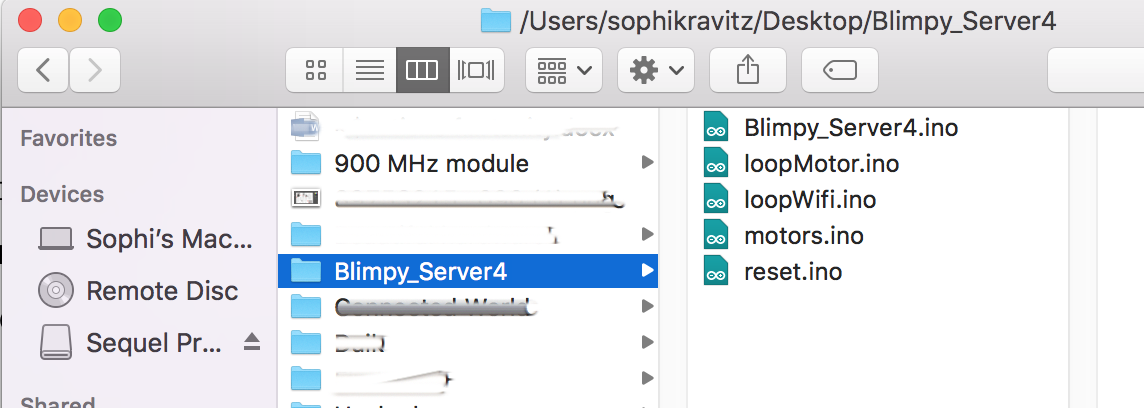
- Open the Arduino IDE and load in the blimp server file. Your Arduino folder should look like this:
![]()
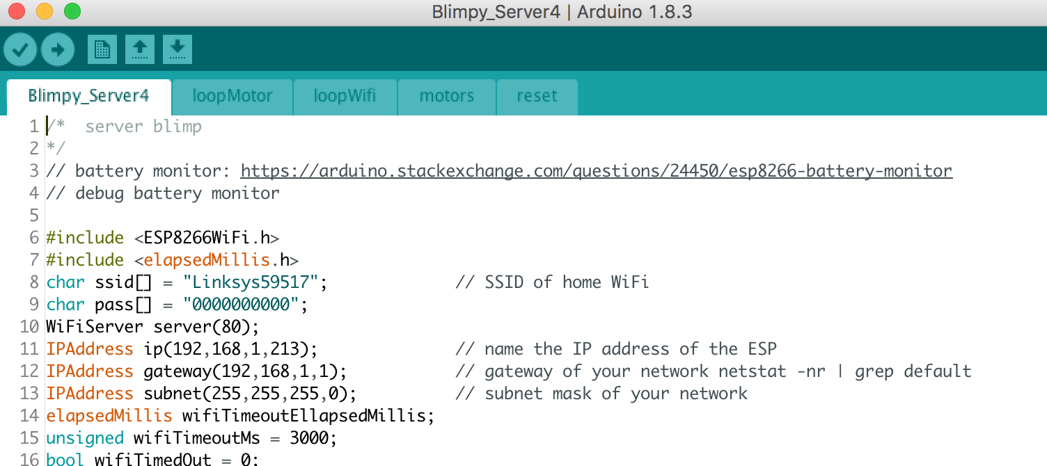
If your folder is organized like the above, when you open the Arduino file Blimpy_Server4.ino, it will look like this:
![]()
You can also put the file into one long thing rather than breaking it up. I find it easier to stay organized with tabs for different sections of code, but YMMV.
Please note: you will need to add in your own SSID (line 8) and password (line 9). I use a local router which isn't connected to the internet (best) but you can use any router.
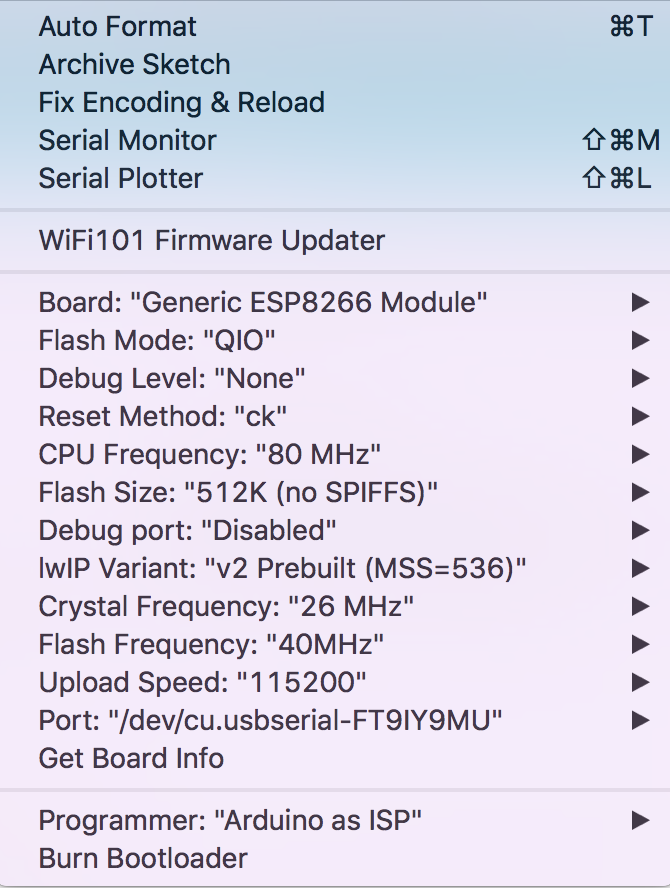
SETTINGS FOR ARDUINO UPLOAD
Tools > module > board: Generic ESP8266 module
Port > tag-connect, will have a few numbers
Programmer >Arduino as ISP
![]()
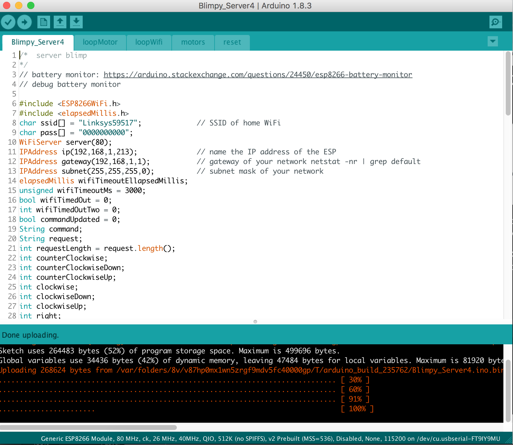
Once you've got all of that set up, you can upload! You'll see a line of dots appearing on the bottom of the Arduino IDE until it reaches 100%.
![]()
That's it!
The above directions are just for the blimp board itself (server). You'll need to upload the client to an Adafruit Feather ESP32, but that's quite straightforward.
-
Optimized layout + proportional controls
10/06/2018 at 00:10 • 0 commentsWhen I last left this project the great things were:
- It flies and the weight issues are over
- Up/ Down/ forward controls perfectly and the blimp moves clean
- It flies! It flies It flies!
The bad things were:
- There's a power issue. When the motors turn on, they suck power, causing the regulator's output to sag. This should be fine, because regulators are supposed to REGULATE, but this one takes too long to recover (like 5 uS) and the ESP loses connection. I had added a large capacitor at the regulator input which helped a lot, but didn't cure the problem entirely.
- Left/ right do not control nicely at all, and after a number of experiments with rudders, I think it's because of the overshoot with on/off controls.
________________________________________________________
I made a new board, changing the layout slightly so that the power traces are closer to the source (battery). I'm hoping that this results in more stability.
I also added a PWM output on GPIO0 and GPIO2. For those unfamiliar with the ESP8266, GPIO0, 2, and 15 need to be in a high or low state on boot in order for the program to run. It's actually really easy to make these GPIO work and on the bench this works very well. I anticipate challenges when rebooting while in the air.
Motors can now move more slowly with PWM.
This weekend's task is to test out these cute proportional joysticks I got from Adafruit.
![]()
-
Great disappoint and voltage sag
06/27/2018 at 16:00 • 3 commentsI presented on this project at Hackaday Belgrade (I'm at 1:44:32) and had it working just enough to talk about :)
I still have a couple of issues to work out, and one of them turned out to be a huge bummer.
- Two of the motors (both on same driver #1) spun at slower rpms than the one (on second driver #2).
- I looked at the driver chip under the microscope and noticed that I'd soldered it slightly off the pad so that the junction provided half a trace-width (6 mil not 12 mil). Side note: I cannot find where the trace units are in Eagle. I assume since my board is in inches, the traces are too...
- Fixed this by removing and re-soldering the chip
- Now that all the motors draw the same current (about 350mA max each at 3.8V - 4.0V), new power problems arose. I noticed that the ESP kept resetting which indicated that the voltage was dropping below 3.0V for some short length of time (5us).
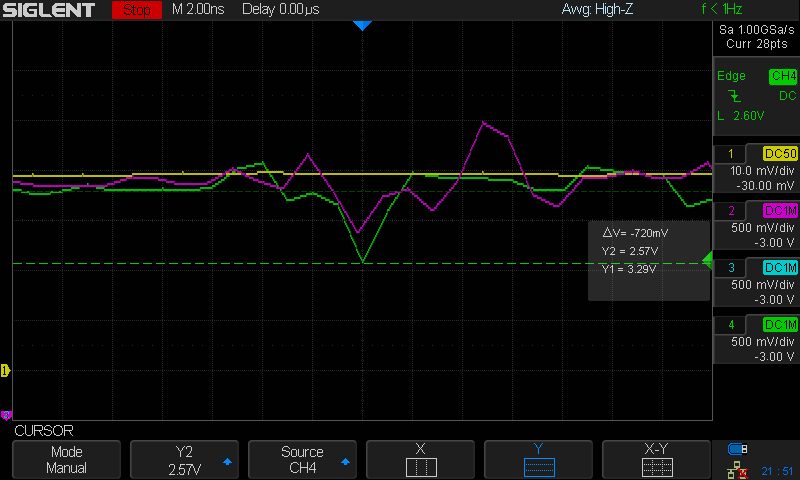
Last night I worked with Ed Nisley, a great friend and an engineer with better tools than I, to discover what exactly was going on. Ed has a Tectronic device from the 70s which coupled with a hall effect sensor converts the signal to a current value to be viewed on a scope. We looked at the current (in yellow), which fortunately doesn't dip under load. However, at the point of reset, with all three motors running (one shown here in purple) + the ESP8226 reaching out to WiFi (1.2A) we observed a voltage dip down to 2.6V at the ESP8266 supply/ buck-boost output (green).
![]()
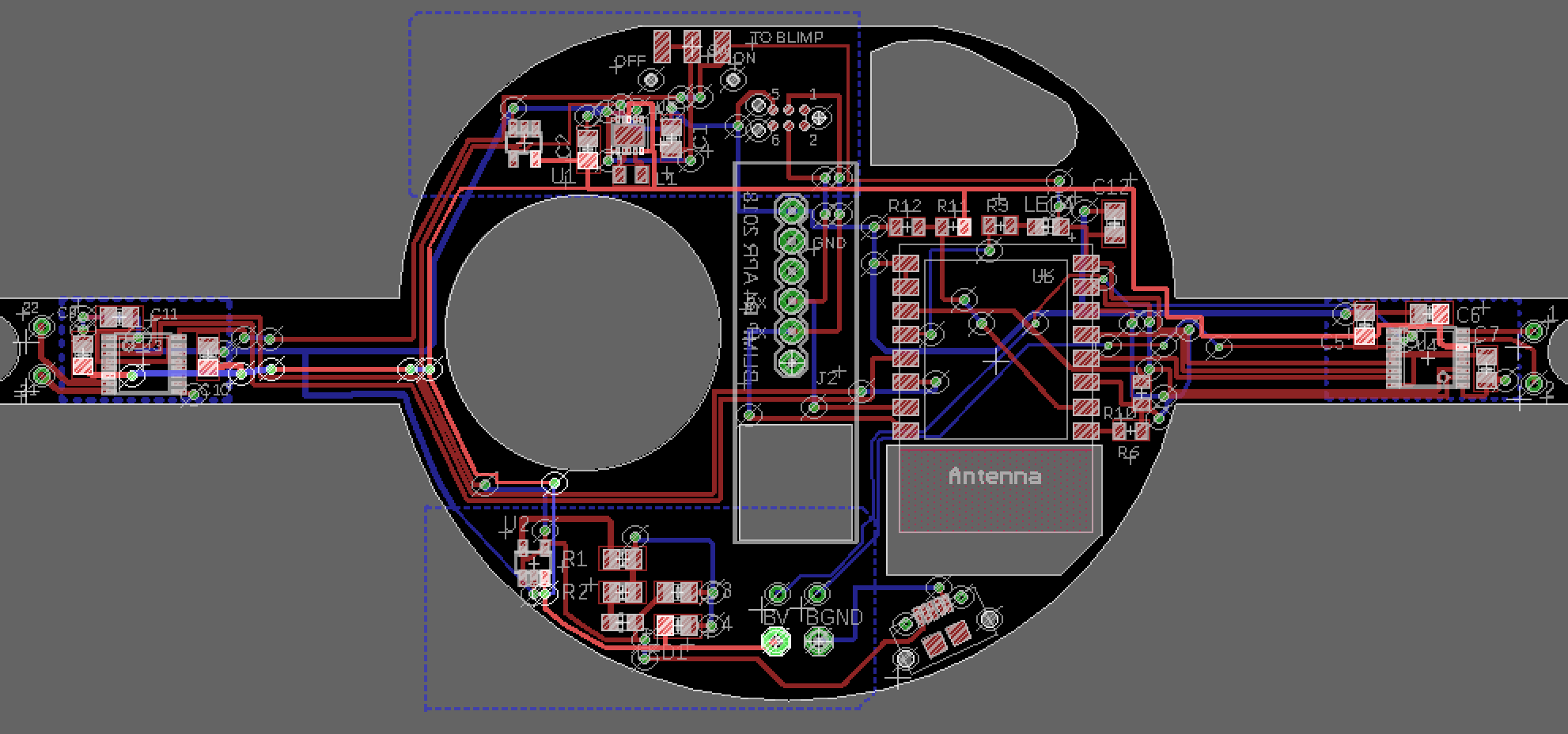
This could be because the back emf is going back into the voltage supply due to such long traces on the board. A little hard to see, but the highlighted trace is the battery supply trace.
![]()
I'll recreate some of this test and post scope pictures later. My plan to troubleshoot is to solder three fat wire paths over the board: a path directly from battery supply to buck boost converter + battery supply to each driver.
For now, this is a pretty big bummer as if this is the case, I'll need to redo my layout to put the buck-boost (top left) converter much closer to the supply (bottom middle).
Stay tuned...
- Two of the motors (both on same driver #1) spun at slower rpms than the one (on second driver #2).
-
Second Flight!
05/21/2018 at 18:35 • 2 comments -
Blimp User Controls (part 1)
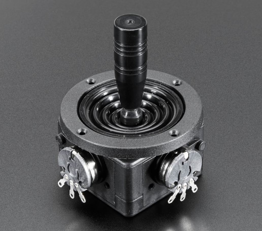
05/18/2018 at 16:22 • 0 commentsI'm going with a joystick for the main controls because everyone knows how to use one. A joystick is primarily used for direction and speed, it should be received well as a participant interface.
I need 6 commands minimum (up/ down/ left/ right/ forward/ back) and the joystick that I chose is made up of 4 microswitches, so only 4 controls. I love arcade buttons, so I decided to add 2 of those.
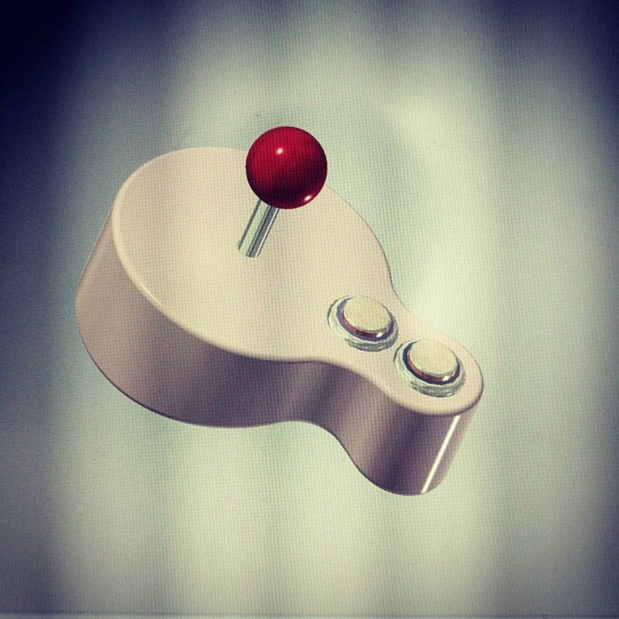
Inside of the controller is an Adafruit Feather (has an ESP8266 on it) and a battery.
I used Inventor to model this. Already realized that this rev 1 is missing holes for the battery charging and a reset switch. I also should have added screw holes on the bosses to make them less hollow.
I can fix these post print though :D
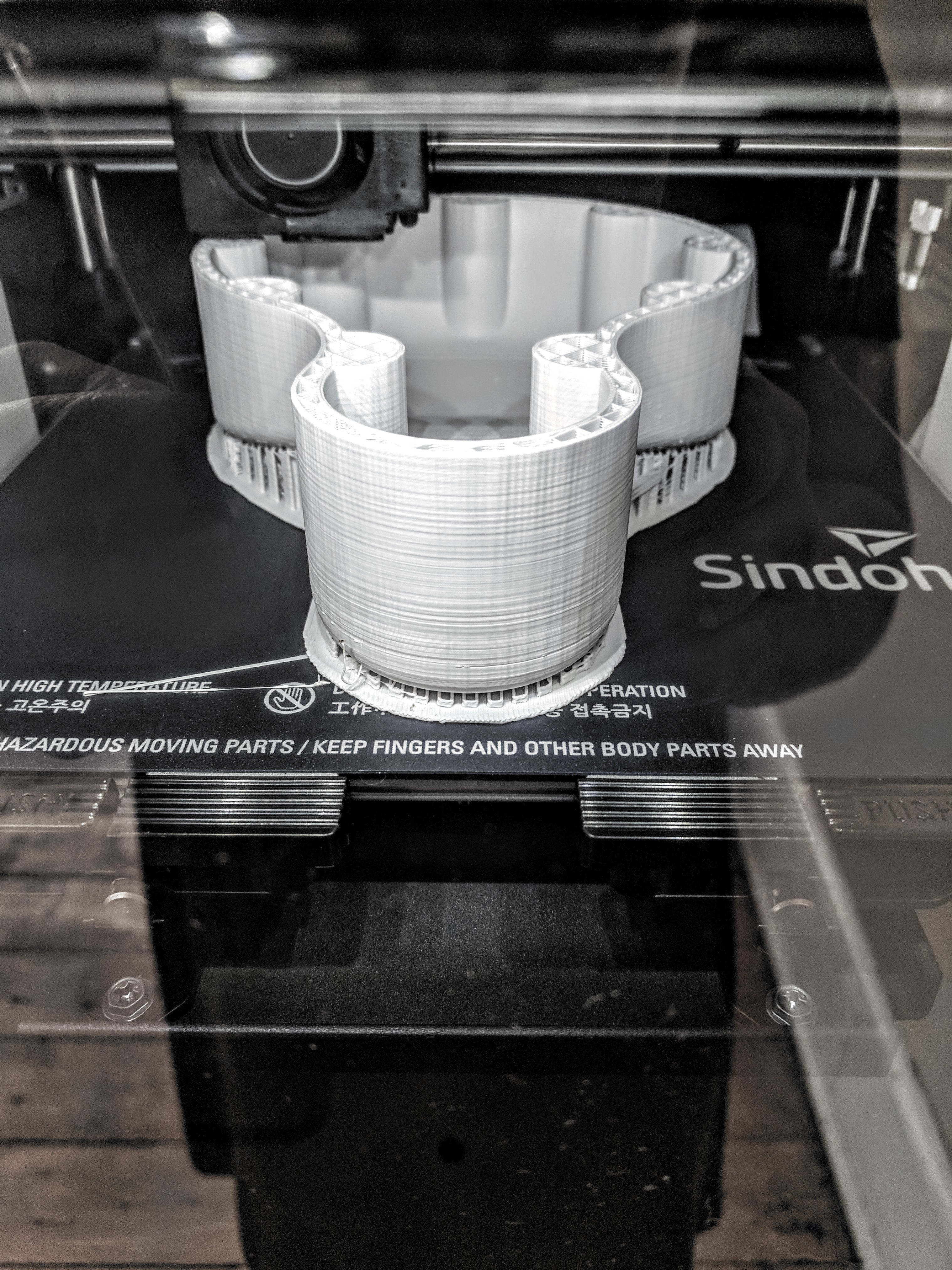
![]()
and started printing last night. It looks good so far!
![]()
-
It flies, now what?
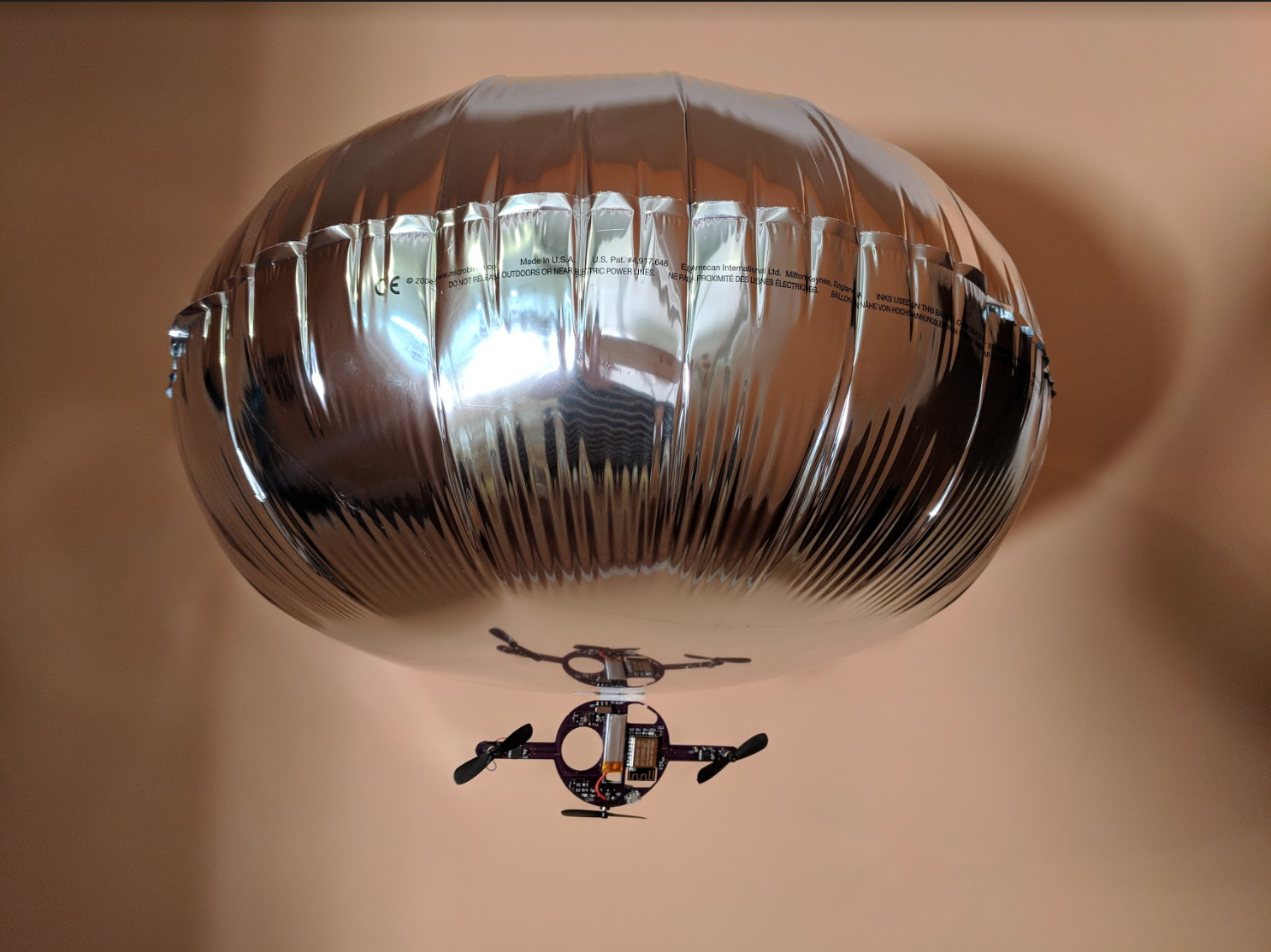
04/23/2018 at 02:36 • 4 commentsI'm pretty excited. The blimp flies and is as controllable as a large envelope full of helium in a drafty house can be ;)
![]()
The blimp shown here is 24" diameter, 8" high.
So what's different about this revision and why does it fly?
- Motors are spinning super fast and drawing about 200mA each.
- New motor drivers provide motors with battery voltage, but control voltage is separate, allowing for motors to get maximum power.
- Board is 0.8mm thick and cut the weight of the PCB in half - thank you @oshpark!
- Buck boost converter is slightly on the edge with allowing 1.3A, but is much more capable than the voltage regulator in earlier revisions.
- Code has been revised so that there is no lag between control switch and motor.
Gotchas
I had a memory leak in which the ram was spinning down and causing the connection to drop. Turns out the libraries (2.4.1) provided for ESP8266WiFi have a bug. A down rev (2.4.0) fixed that problem, but it still took me a day to figure it out.
Still todos
- Evaluate battery draw with special wattmeter designed to look at single cell draw
- The hardware is there to measure battery levels, add this to code and send signal when low.
- There are still connection loss issues, hopefully adding error handling to code will address this.
- FUN! Design controller for joystick and buttons. I'm envisioning a figure eight so that it fits nicely in the hand.
- Test with 24" blimp when that arrives
- Add ESP reset switch or button to gondola hardware
- Add ESP reset switch of button to joystick hardware
I found these docs helpful
-
Tiny motor thrust
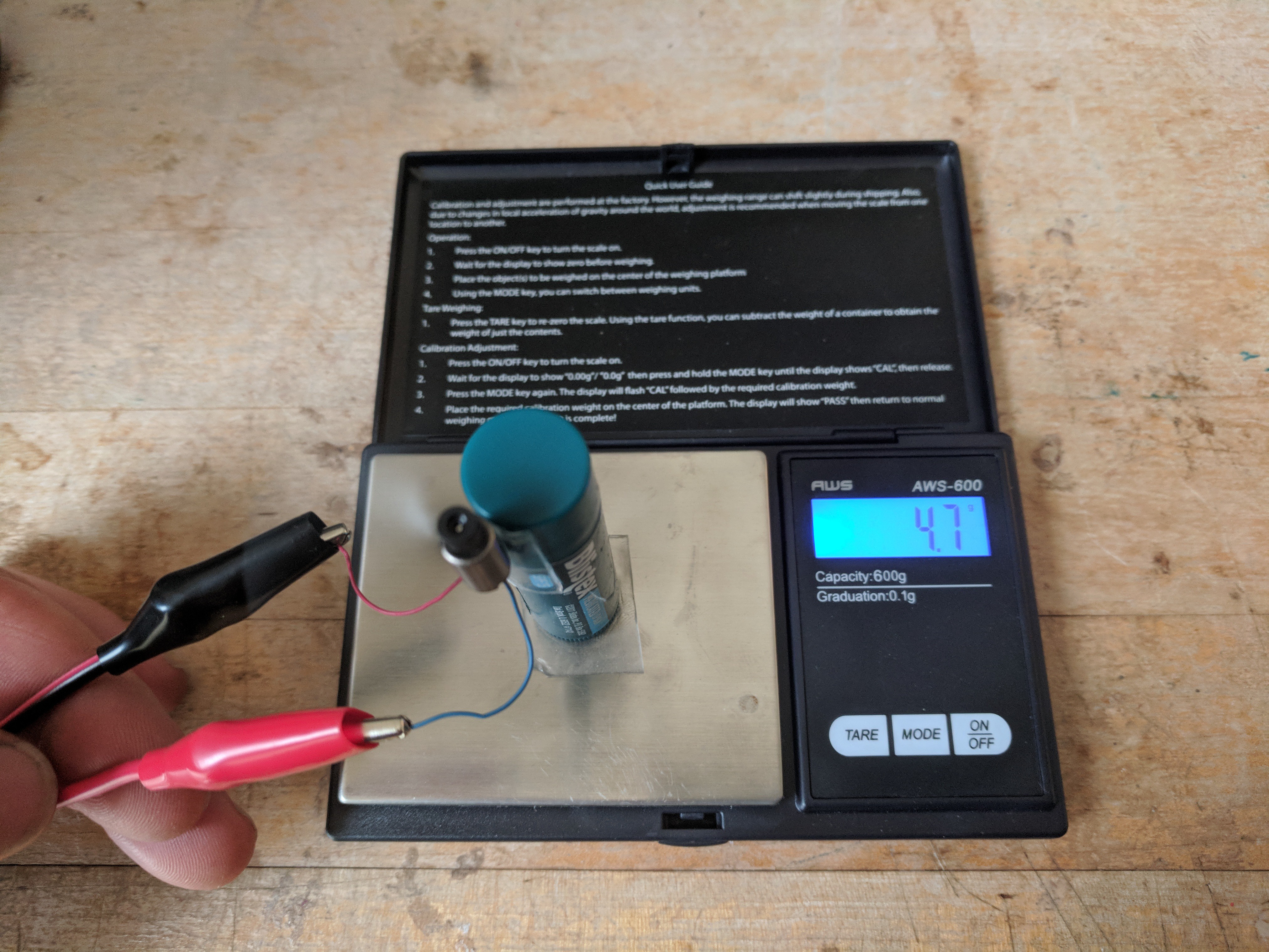
04/05/2018 at 17:06 • 1 commentForgot to mention that I measured thrust the other day. This is a 3.7V motor at 40,000 rpm.
Nontechnical way to describe thrust is the amount of force (unit grams) it takes to move the mass (blimp gondola) out of the way.
The real definition is the perpendicular force to the load measured in newtons, or the amount needed to accelerate 1 kilogram of mass at the rate of 1 meter per second per second. Source: wikipedia
![]()
-
Blimp rev 3
04/05/2018 at 01:01 • 4 commentsPutting this PCB together has been quite a journey.
While soldering QFNs I broke down and purchased a microscope and a hot air tool. The hot air tool was really cheap and is already loudly rattling after only a month in the shop.
I just received a board back from @oshpark that has some new accoutrements:
- 0.8mm thickness
- Tag Connect connections! (working!)
- ADP2504 buck boost
- SOIC footprint motor drivers
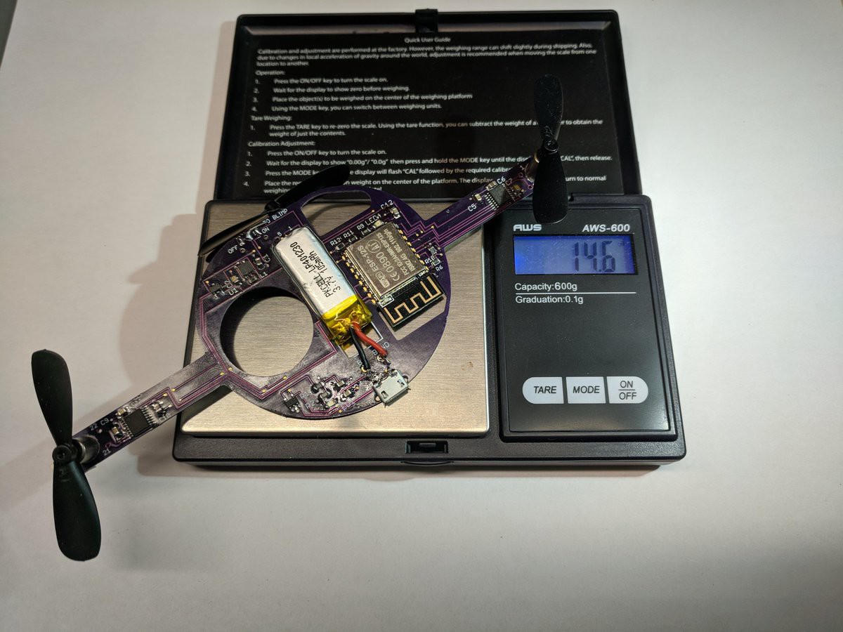
It is all working well and it is the correct weight.
![]()
Things to fix in next rev:
- Connect PGND (pin 9) on motor drivers to ground (FACEPALM)
- Connecting points for the motors are covered in solder mask (??)
- Fix lag in comms between joystick and blimp (code? power problems? idk)
- Measure current accurately with Astro Flight Wattmeter to get sense of battery curve
-
Gotchas WTF
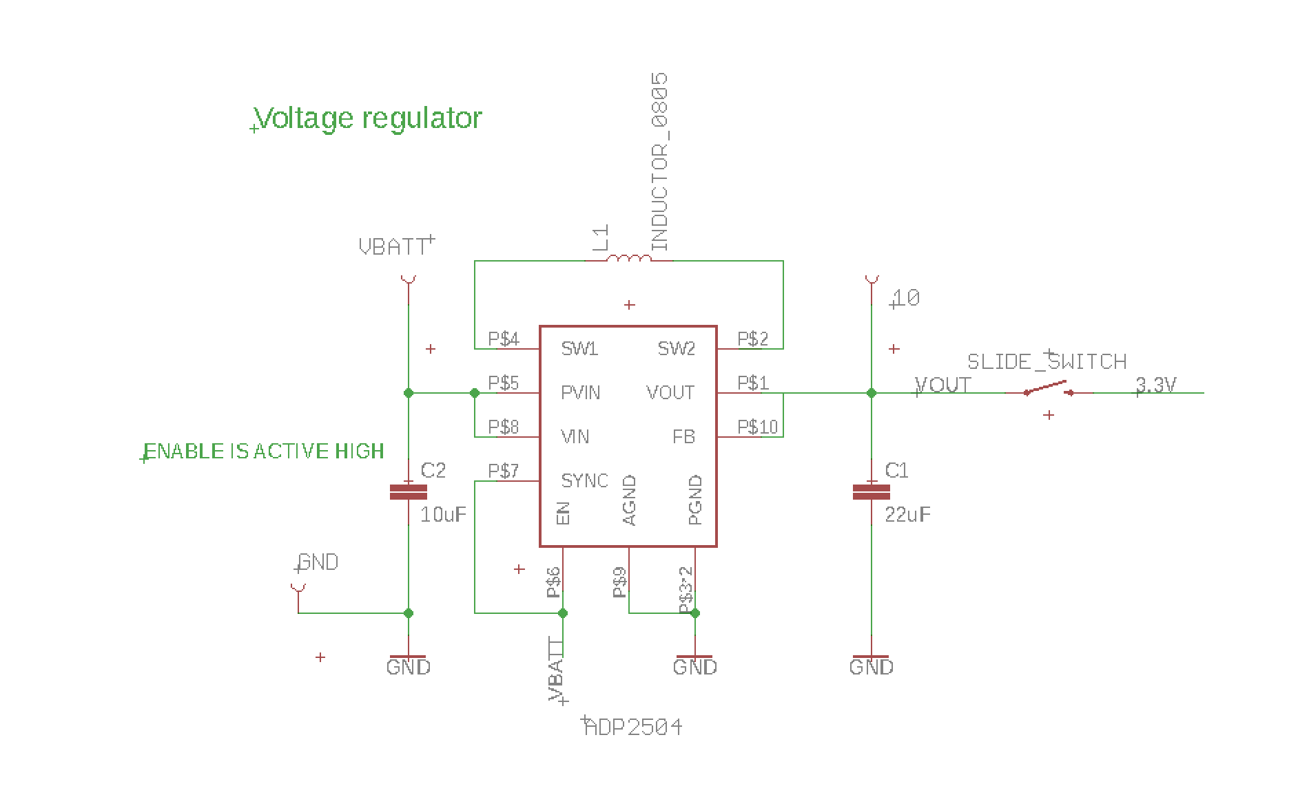
02/09/2018 at 17:50 • 7 commentsI designed an intermediary board to test out a new buck-boost voltage regulator, new motor driver, and a tag connect cable. For those of you in the ESPxxx forum, this is v2 intermediary board with EN tied to VBATT.
Here's the schematic, and the layout.
I intend to run the board with a single cell Lithium battery no less than 3.6V.
For testing, I am using a benchtop power supply (adjustable V, 3A) or a wallwart (5V, 1.6A).
The new voltage regulator, ADP2504, can provide a current output (see diagram on page 6) of over 800mA at VIN 3.6V. The inductor is rated for 700mA. Capacitors are X5R type.
Screenshot of ADP2504 schematic::
![]()
So far, I have populated the board with the ADP and the ESP-12S.
These two weird things are happening:
With power input from benchtop > 4.6V, ESP is able to program and hold the program. Under 4.6V, it is iffy, meaning that the program does not run all the time. Same (expected) results with wallwart at 5V.
Current draw after ESP reset is less than 60mA, but sometimes (often at lower voltage) the current draw jumps up to as much as 210mA.
Does anyone have an idea why this could be happening?
UPDATE: benchtop power supply is wonky and gives inconsistent readings, shuts off randomly, and probably puts out inconsistent power. My best guess is that its constant current output is stuck on something not desirable. I've had it for over 8 years, so....
To add to the gotchas:
- New Macbook Pro is incompatible with anything FTDI (seriously WTF)
- Fluke 16 measures a full 0.1V higher than the benchtop - no clue what is accurate now.
- 3VDC wall wart with indecipherable 2008 cell phone end now chopped off puts out something definitely not 3V!
- Brand new air gun is making a horrible death rattle.
*******************************************************************************************************************************************************
The ESP8266 can source 12mA on each GPIO pin. Maximum Drive Capability spec page 15.
Grabbed this from the forums:
12mA per pin source
20mA per pin sink
Total: 12mA x 16 GPIO
![]()
Remote Control Mini Blimp!
Mini blimp flies through hoops! Features 3 DC motors/ propellers, battery charging, and wireless communication.
 Sophi Kravitz