-
New PCBs! (New display + power hub)
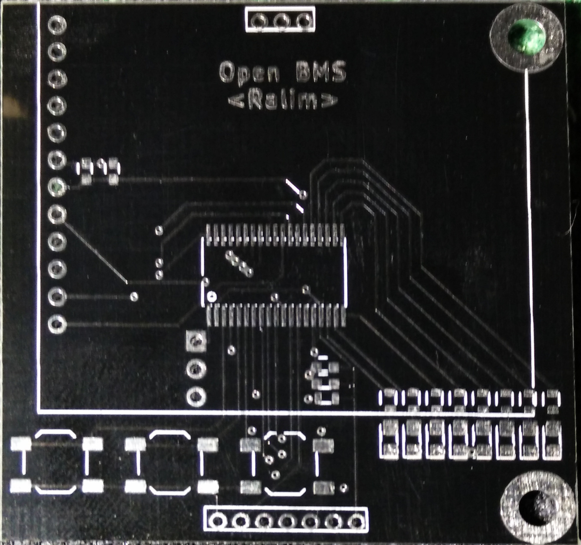
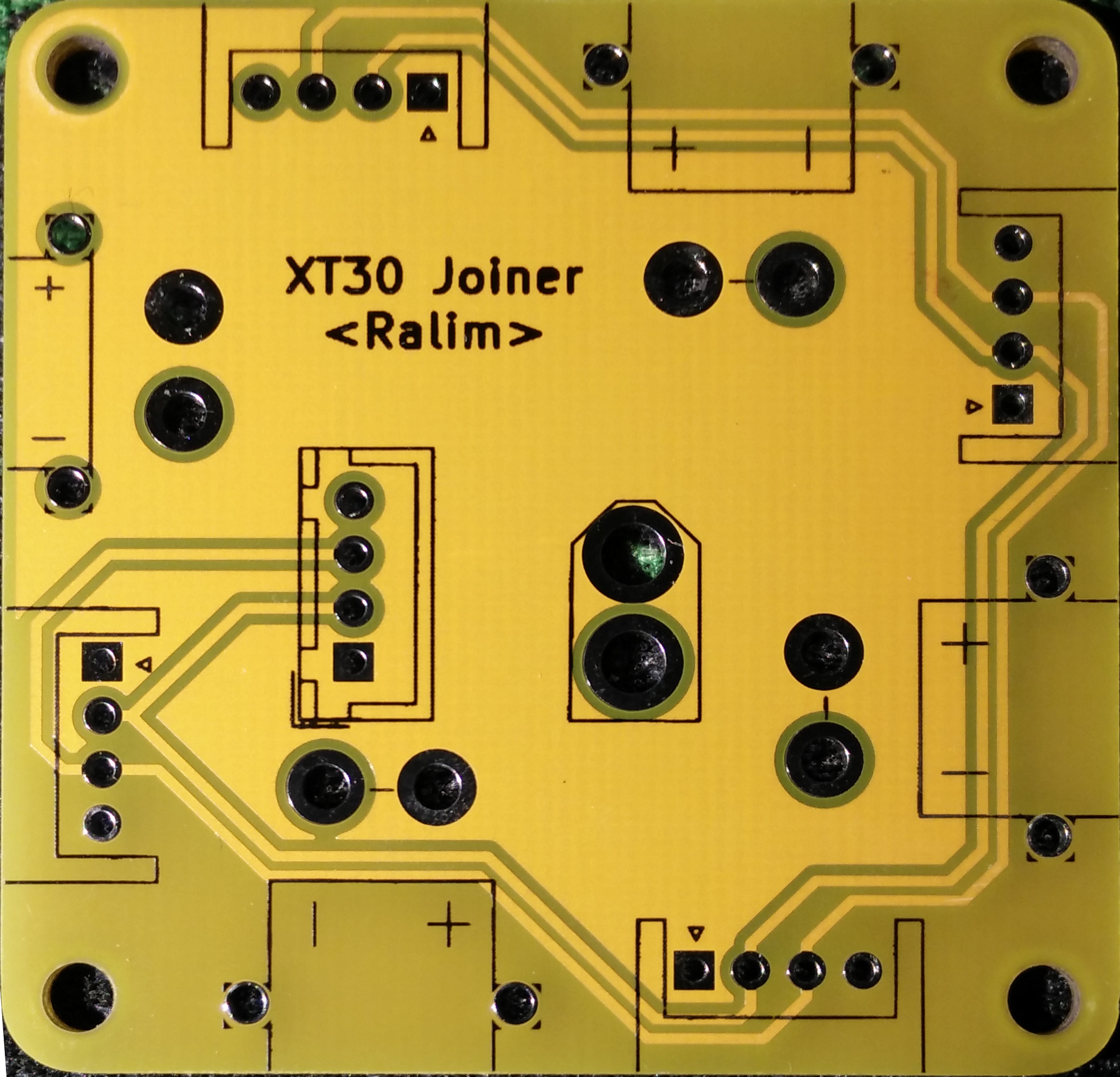
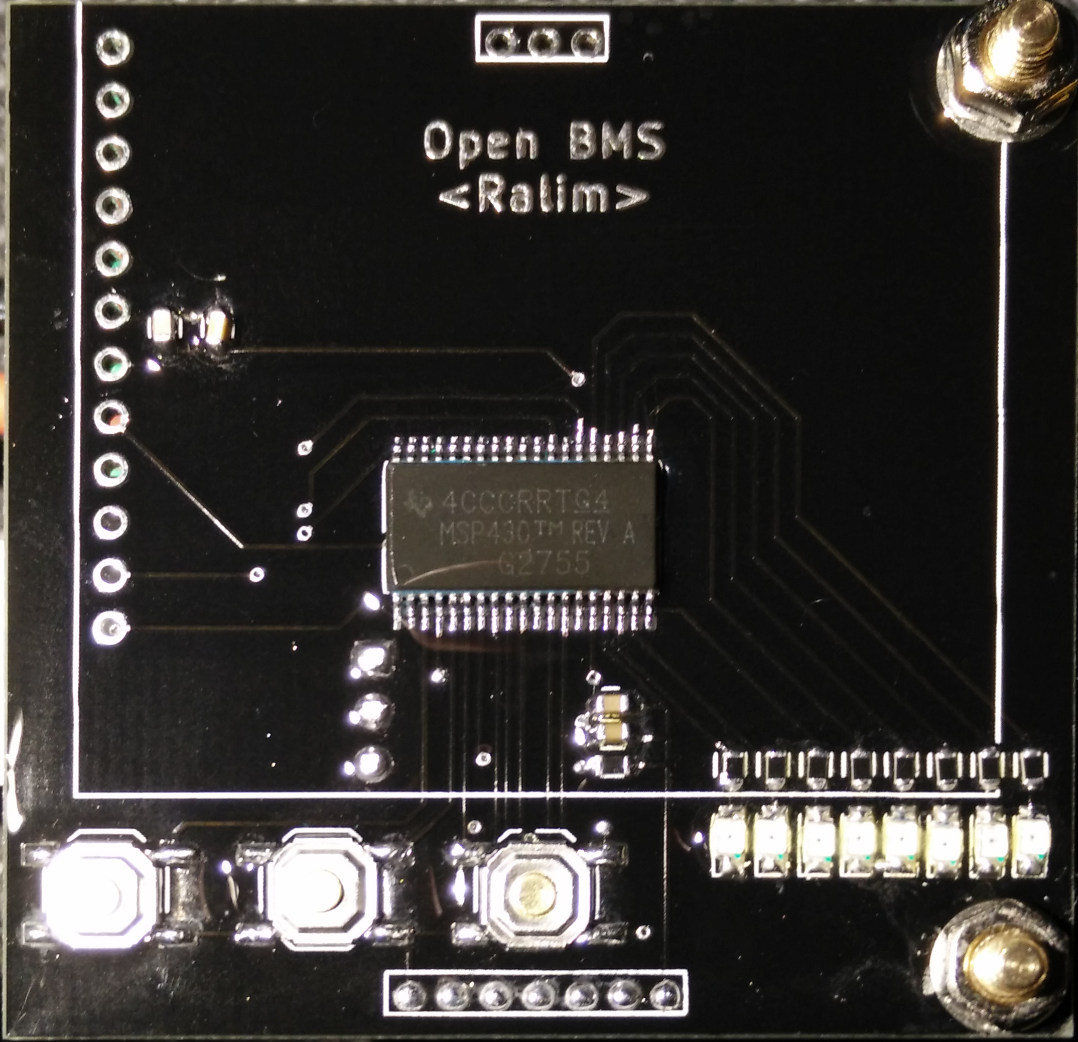
08/16/2017 at 10:32 • 0 commentsThe awesome free PCBs from Elecrow arrived this morning. Around 2 weeks for the delivery (to Australia). Which is the same or faster than OSHPark. I ordered 5 each of the new display board (In black soldermask) and the XT30 hub (In yellow). I recieved 7 of each, which was a nice surprise :)
I will be doing a small review video on the board quality as part of the deal for the free pcbs. However initially I am very, very impressed with the quality. I was expecting a lot worse for the money ($5 USD per set). However they are really quite good. Not the amazing gold of oshpark, but overkill for almost all of my projects. All the traces looked good with no copper issues. The solder mask on the yellow is really nice. Its more of a mustard yellow or burnt gold. Sort of a pity its not just a little bit brighter to match the XT60 plugs. Nothing on these boards would have pushed the technology at all, but they did turn out well.
Only slight issue is the black solder mask flakes of a little bit easily. (A little bit visible in the last image, after soldering). But I do also use a rather scratchy soldering iron tip.
Now its just waiting for the LCD to turn up and alot of code to write :)
![]()
![]()
![]()
-
Revised front panel sent off
07/29/2017 at 06:50 • 0 commentsElecrow recently offered coupons for free PCBs so I have sent off to them the revised design. This design mostly just fixes the footprint for the MSP430, and also re-arranges the LEDs into a linear line.
Once these arrive back I will review the quality of manufacture as well as hopefully have a working display :)
-
Frontend works!
07/25/2017 at 12:31 • 0 commentsThe PCB's arrived a few days ago, but it took me a day to find the one IC I had left from my two samples.
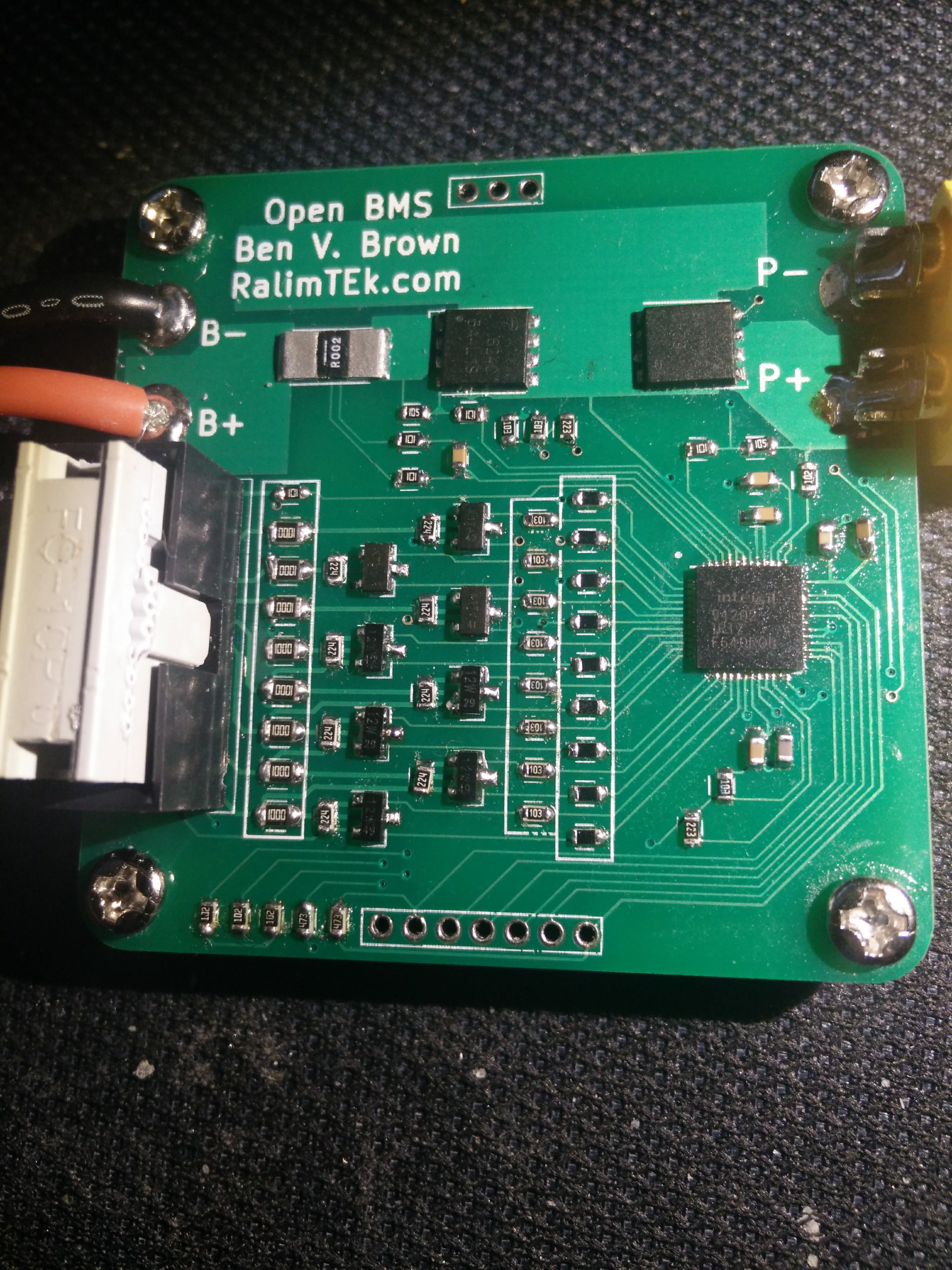
Building the board was a fairly normal deal, I used hot air to mount the ISL and MOSFET, and then just hand soldered the rest with the TS100 with the new C series tip.
Powering up the IC using a current limited supply looked good, and no shorts showed up testing with a multimeter (apart from the jumpers on the back, as I was setting this up for 3S, I had to short all the jumpers).
Once you connect a battery to the balance connector and the main power connector, you need to provide some voltage on the charging input to wake the unit up out of sleep mode.
The AFE powered up and allowed the battery voltage out the first time!
Using the testing code for the Arduino to talk to the unit, I programmed all the settings to suit my Lithium battery packs and the unit seems to be testing well.
After building up the AFE board I realised my layout mistake on the front panel board where I have used the wrong package for the MSP430. Derp.
I will probably send off a new front panel to Oshpark to have a new version made for testing soon.
![]()
-
Initial designs sent off to fab!
07/11/2017 at 12:17 • 0 commentsThe initial designs as published on the Github repository have been sent off to seeed to be manufactured. I have also (attempted) to sample the BMS frontend IC from Intersil which would be rather nice, however if this falls through I will purchase some to test out the design.
More updates coming when the boards arrive (probably 2-3 weeks away now) -
Front panel layout done
07/08/2017 at 09:45 • 0 commentsThe front panel of the unit has been routed and looks to be complete.
This is mostly just a microcontroller with buttons and LEDs.
The plan is to use the 3 switches at the bottom to naivgate and edit the menu, and use the LEDs for status of the system when the lcd is off.
-
Why the MSP430G2755?
06/18/2017 at 07:48 • 0 commentsThe main driving reason behind selecting an MSP430 over other brands / styles of IC was mostly because of the excellent low power modes available. Also I have a fair few of these already around.
This model does not have a DMA so I will eventually be implementing an interrupt based I2C and SPI driver to help speed up communications while keeping the low power that made the IC desirable in the first place.
The LCD I plan to pair this up to needs the SPI interface, so unfortunately if a UART is added for external communications, it will be using a software driven driver instead of the hardware.
The plan is the have the LCD screen + 3 buttons to allow for entering and viewing the system status and a rough estimated state of charge (Voltage based initally). If space allows adding a set of LED's is also desired as a method of showing the status from a distance.
-
Rough Design of Frontend
06/18/2017 at 07:16 • 0 commentsThe rough design pass of the front end has been completed.
This is mostly based on my previous breakout board for this IC, which was just a transfer of the EVM with only single path mode supported. Also pre-charge support is dropped due to size constraints.
This design adds support for all 8 cell inputs on the IC, and converts the balancing connection to a 2x5 0.1" header block. This was done mostly as JST XH connectors take up a lot of room, and this allows for an IDC connector to be used if desired.
The Power In/Out connectors are using large wire holes, with a spacing to allow an XT60 to also be soldered on if desired. I would recommend a 12 AWG breakout cable be used to reduce the stress on the PCB during plug/unplug events.
A small 2.0mm pitch header is used to provide a mount for the GUI board (Yet to be designed), and M3 mounting holes round out the design.
 Ben Brown


