 iliasam
Video demonstrating results of reverse engineering of X-40 laser tape measure:
Connecting laser tape measure to Arduino:
Rebuilding cheap laser tape measure to universal laser rangefinder
Already have an account? Log in.
To make the experience fit your profile, pick a username and tell us what interests you.
Video demonstrating results of reverse engineering of X-40 laser tape measure:
I had published firmware and source code for modern B2A laser tape measure modules:
https://github.com/iliasam/Laser_tape_reverse_engineering/wiki/B2A-laser-rangefinder-modules
I have bought cheap Chinese "X-40" laser tape.
I disassembled it and found that it is really contains laser module that I reverse engineered earlier:
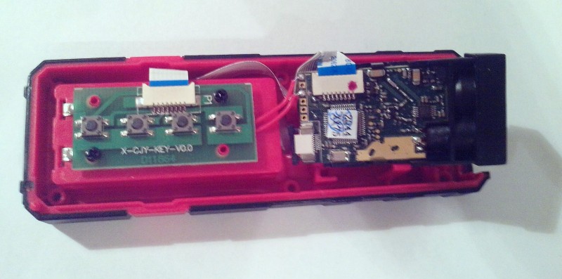
But the module version is "701A", it's not like "512A" that I bought earlier:
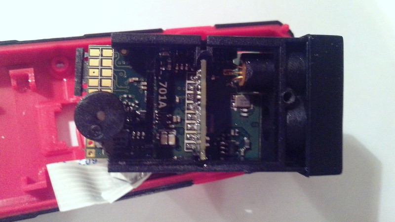
It can been seen that some components are placed at another places.
I want to continue reverse engineering: measure some parameters like APD voltage, desolder some SMD components and measure their values. It can help me to increase parameters of laser rangefinder module.
I have tried to switch laser modulation frequency to lower frequency.
I have tested several frequencies. The lowest frequency still was working fine is 25 MHz. I found that amplitude of signal decrease to 0.65 of initial value (at 150 MHz).
I think that I need to make additional configuration of Si5351 PLL to set modulation frequency to lower frequency. My target is to set modulation frequency to 15 Mhz.
Why I need lower frequency? To increase unambiguity distance - at 15 MHz is would be 10 m.

The 512A and 701A seemed to be both made by a company http://www.jrtmeasure.com/
Here is a link to the 703A manual which I believe is the same for the 701A
https://www.dropbox.com/s/q4x5ru2hvwp5bf0/703A%20user%20manual.pdf?dl=0
I am thinking about ordering the 512A DIY kit from AliExpress.
Were you able to use the TX and RX connections to send Commands to the 512A DIY kit? Or is the serial communications locked out. ( I'm wondering why the DIY kit is cheaper than the stand alone TTL module?)
The same question goes for the 701A that came from inside the x40 laser measure.
Are you able to communicate with the 701A module, (using the manual i linked), or is the serial communications locked out?
I got a price or $35 direct from JRT for the 701A, but that doesn't include shipping.
Thanks so much,
D
I was playing with a 703A that I had bought on aliexpress as a standalone. Soldering onto the pads was annoying so I decided I wanted the B605B, which has bigger optics for longer range. All of it's connections are through hole. I bought a complete laser tape unit on amazon so I could get it quicker. It appears that the TX and RX are disabled. I emailed JRT and I think they confirmed that only the stand alone units have it enabled. Not sure if the DIY kits would be enabled or not though.
Hello guys i recently bought an 703A from aliexpress https://www.aliexpress.com/item/32793950499.html?spm=a2g0s.9042311.0.0.5c514c4dsLb5Ba, i want to connect on an arduino everything is soldered fine on the sensors and the arduino connections seems right, when i plug in the ARDUINO UNO on the pc the module makes a beep sound (shows me that is alive) but i can't communicate through serial communication with it, the TX/RX based on the manufacturer's manual are open and the module for example want an ASCII in put 'O' so it can open. Does anyone has an idea what i should do? Thanks in advance.