I started, ending last year, to create a physical controller to explore my idea of making a tool for improvisation of electronic music. I didn't have very clear all the theoretical aspects of what I was about to start, but I knew that I had a strong discontempt about the current tools for music performance. At this point I was playing live using Maschine and Korg Electribe.
My first idea was to start creating a sequencer, which for me is the most basic unit for single-man bands. Loopers are the other candidate, but as I wanted to work with musical mutation of the patterns, I thought that sequencers were a better starting point. Also sequencers are much easier to make and tweak since you can output midi events, instead of needing to create analog<-> digital conversions, or having to work deep in DSP.
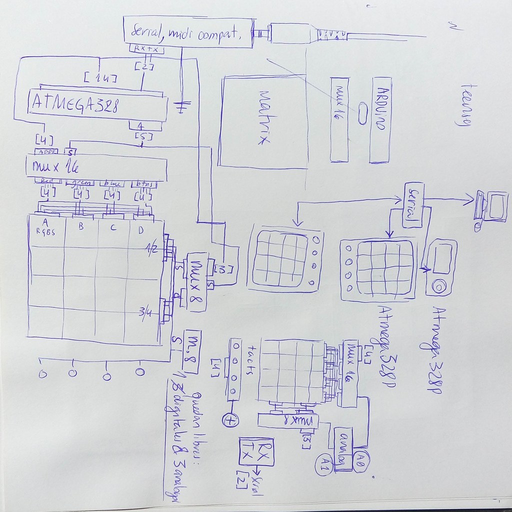
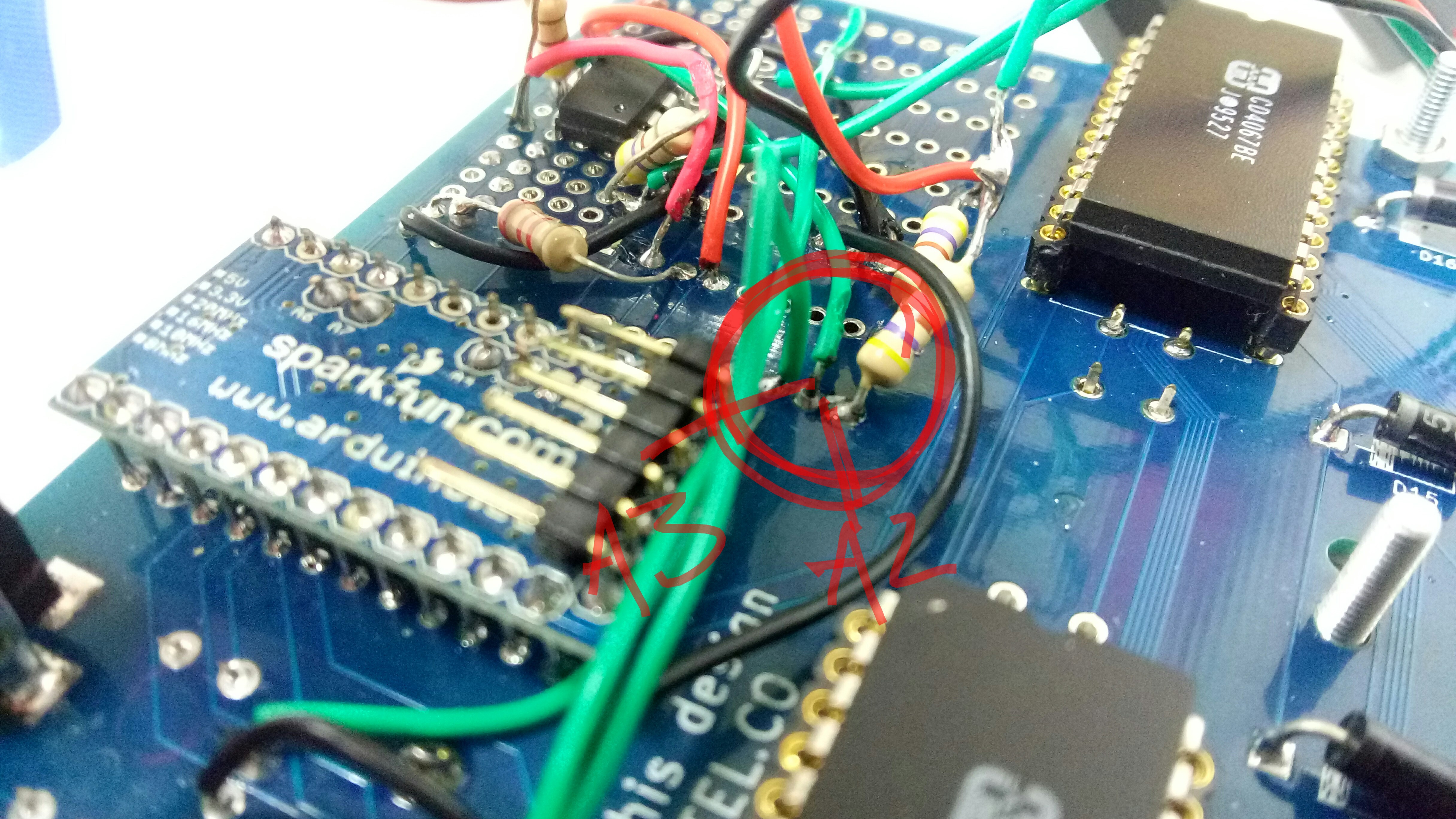
This prototype was soldered in prototype board, using parts from SparkFun. It never worked really well in the proto-boards, because of the amount of cabling that involved. However, I could figure out the schematic that would work, in order to design it in KiCad.
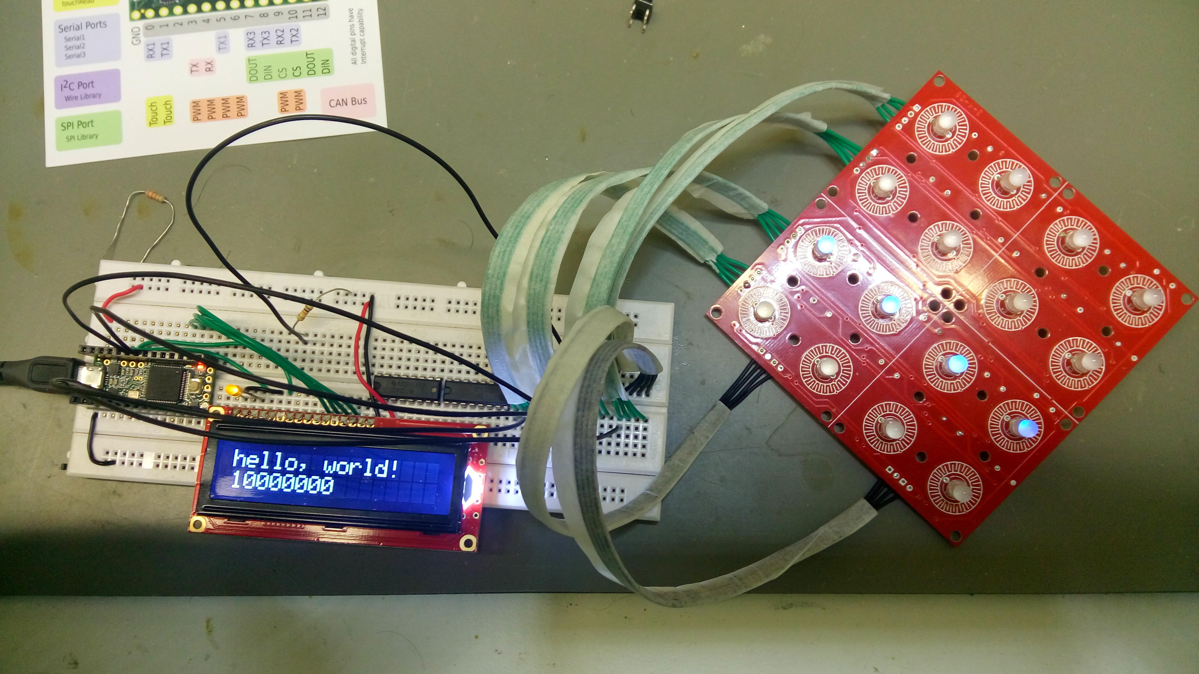
I started using Teensy microcontroller, but I had some trouble writing bytes to the pin ports, and I discovered that when you do a PORTD=something, it maps each byte to a digitalWrite. I know that Teensy has a great processor power, but I found that just too horrible. This, added to the fact that you can't buy the Microcontroller from other supplier because the firmware is not opensource, I decided to use Arduino instead. This ment that instead of using 8-bit multiplexor for the LED's, I needed ones of 16 bits. I discovered that their DIP version is no longer manufactured, but thankfully, Bebek store in Finland had a huge stock. They look really nice, in big, retro package.
The repository I started working in, is now in https://github.com/autotel/thesis-prototype-zero
I tried many different configurations between the microcontrollers and the multiplexors. The best schematic is in the folder thesis-prototype-zero/kicads/try1/ of the repository. Open the version with DIP muxes.pro file of that folder; there you will find the schematic and the PCB layout as well.
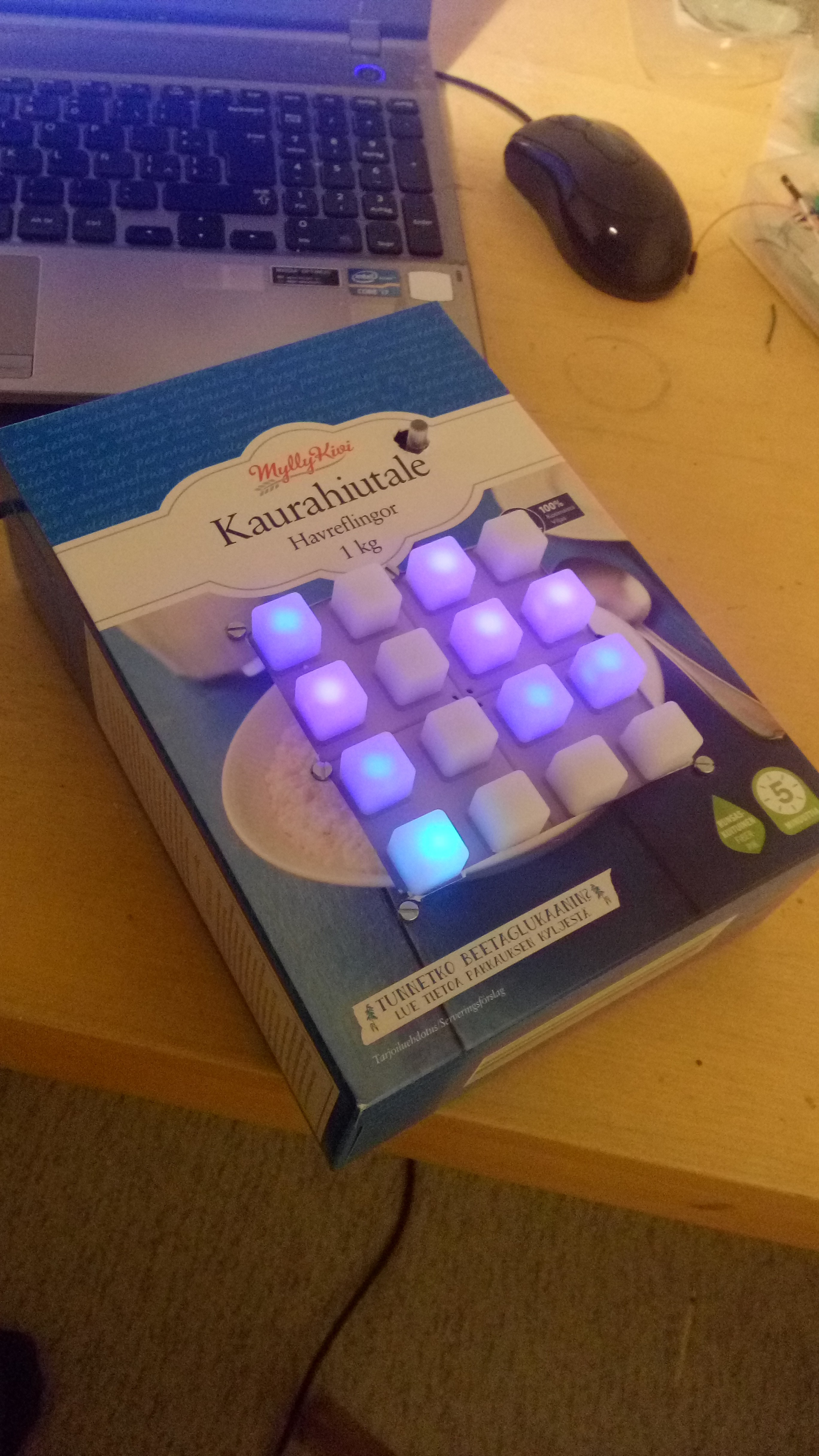
This was the first enclosure I used:
With a bit of time, I did a better enclosure for the soldered prototype. It is nothing more than a bent acrylic:
Then, I designed a board on Kicad and had it done
Seethe solder-protoboard and the manufactured protoboard side by side: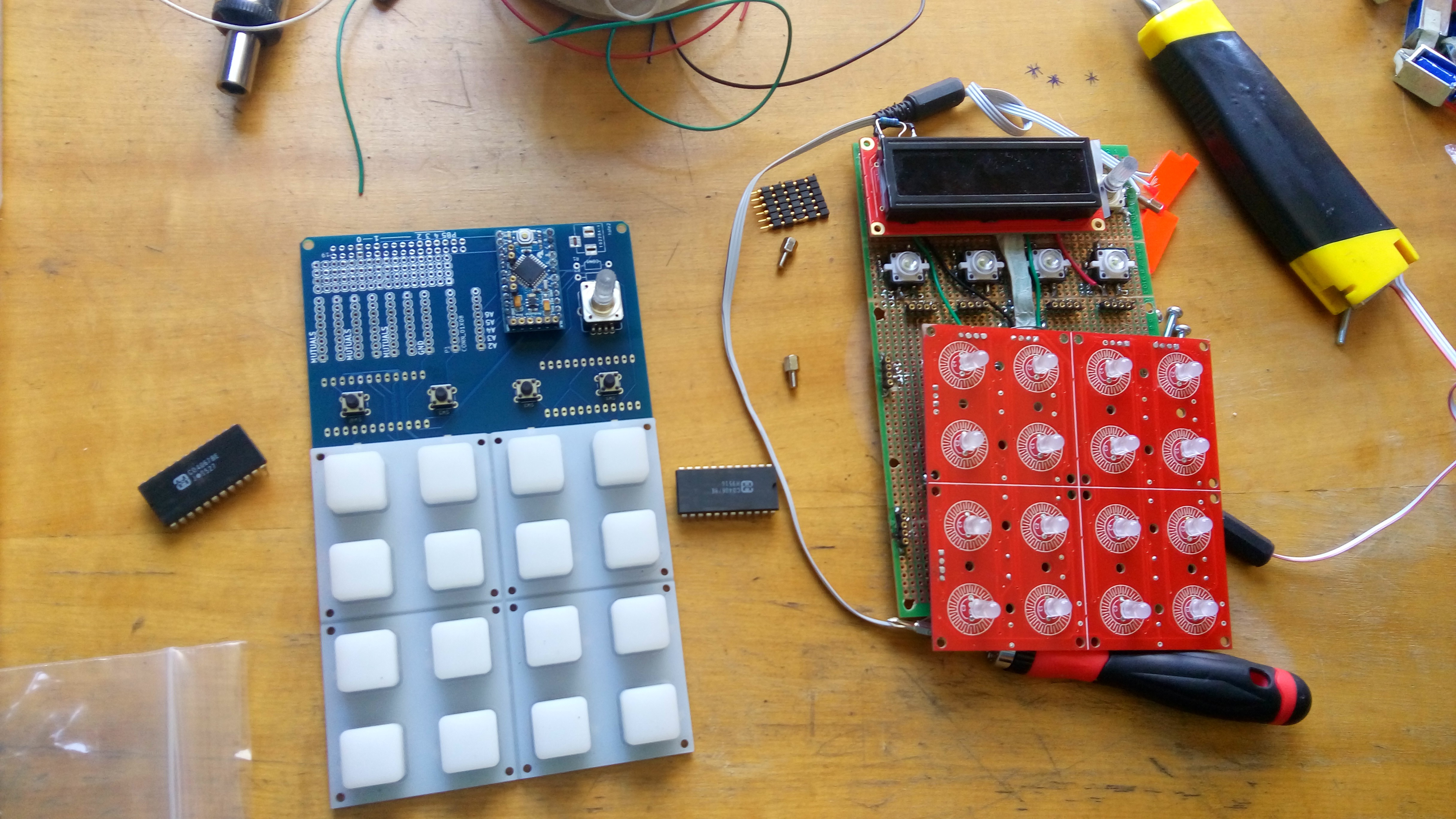
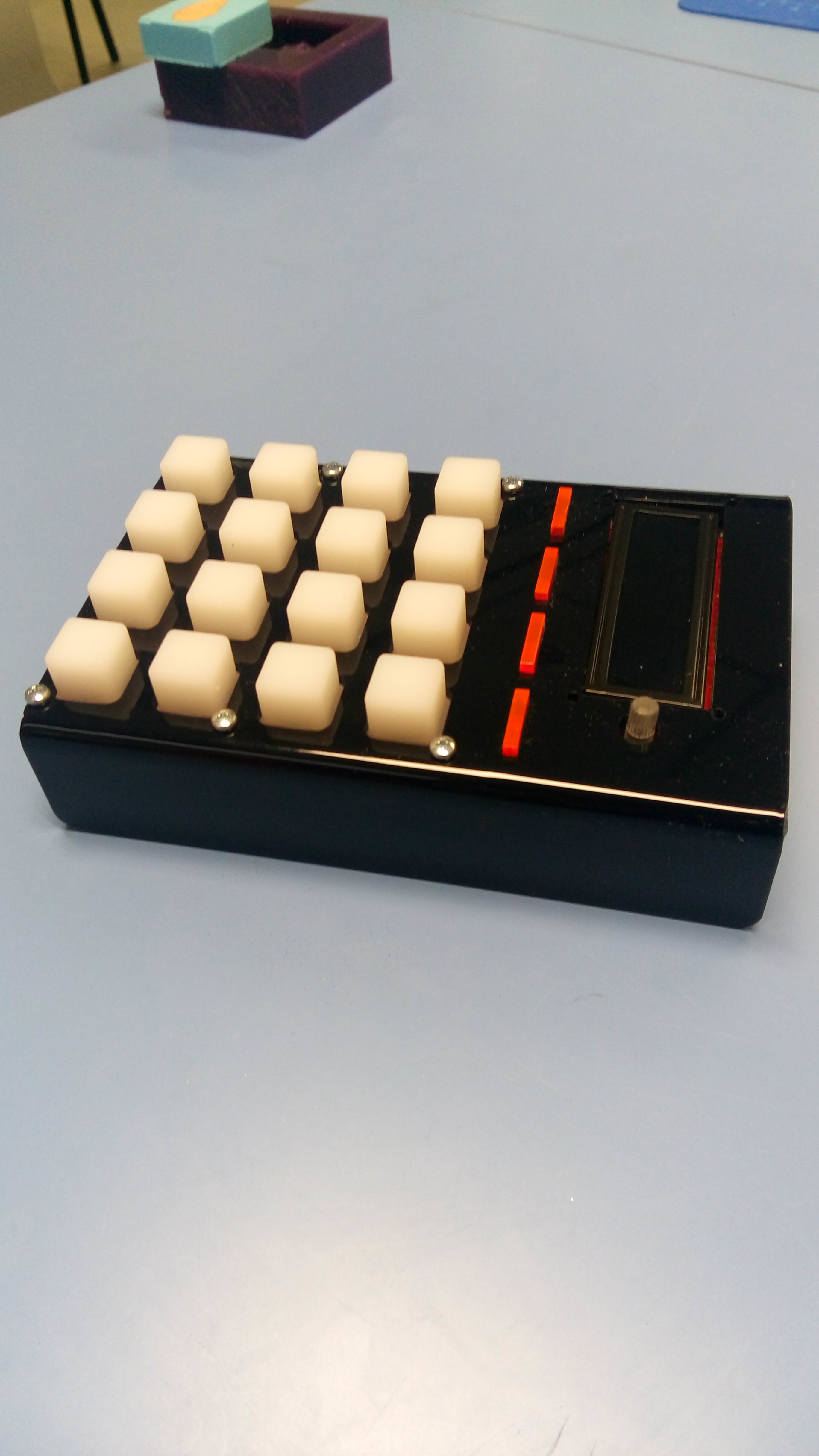
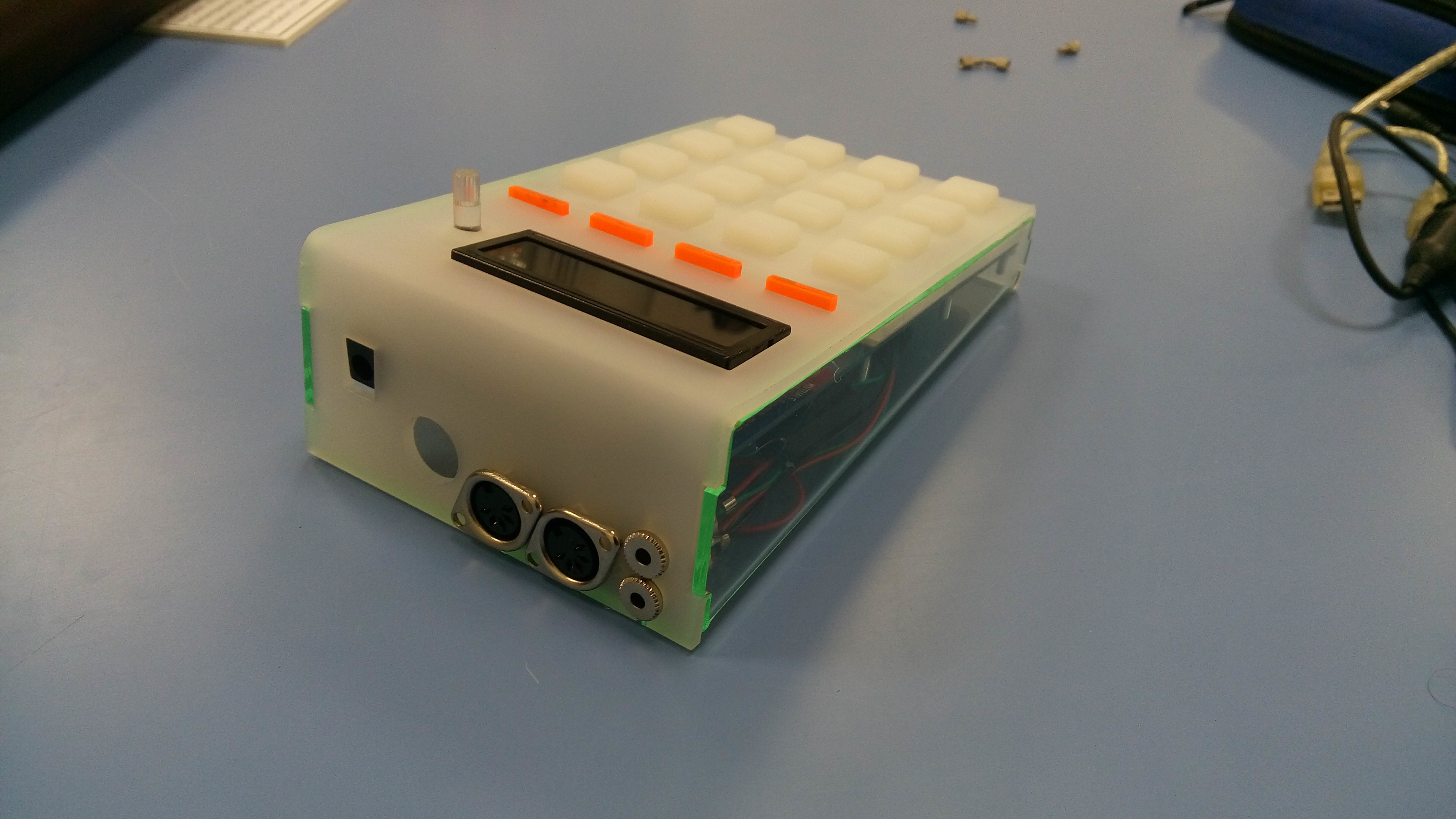
This is the enclosure for the pcb-based prototype. I added midi input and output, plus the respective midi-jack connectors. I ran into the problem that Korg devices have a different pin map for jacks than all the other manufacturers of midi jacks.
see a video where I test how these buttons can sense pressure and serve for nice sound expressions:
Discussions
Become a Hackaday.io Member
Create an account to leave a comment. Already have an account? Log In.