-
Installing Water Mechanism
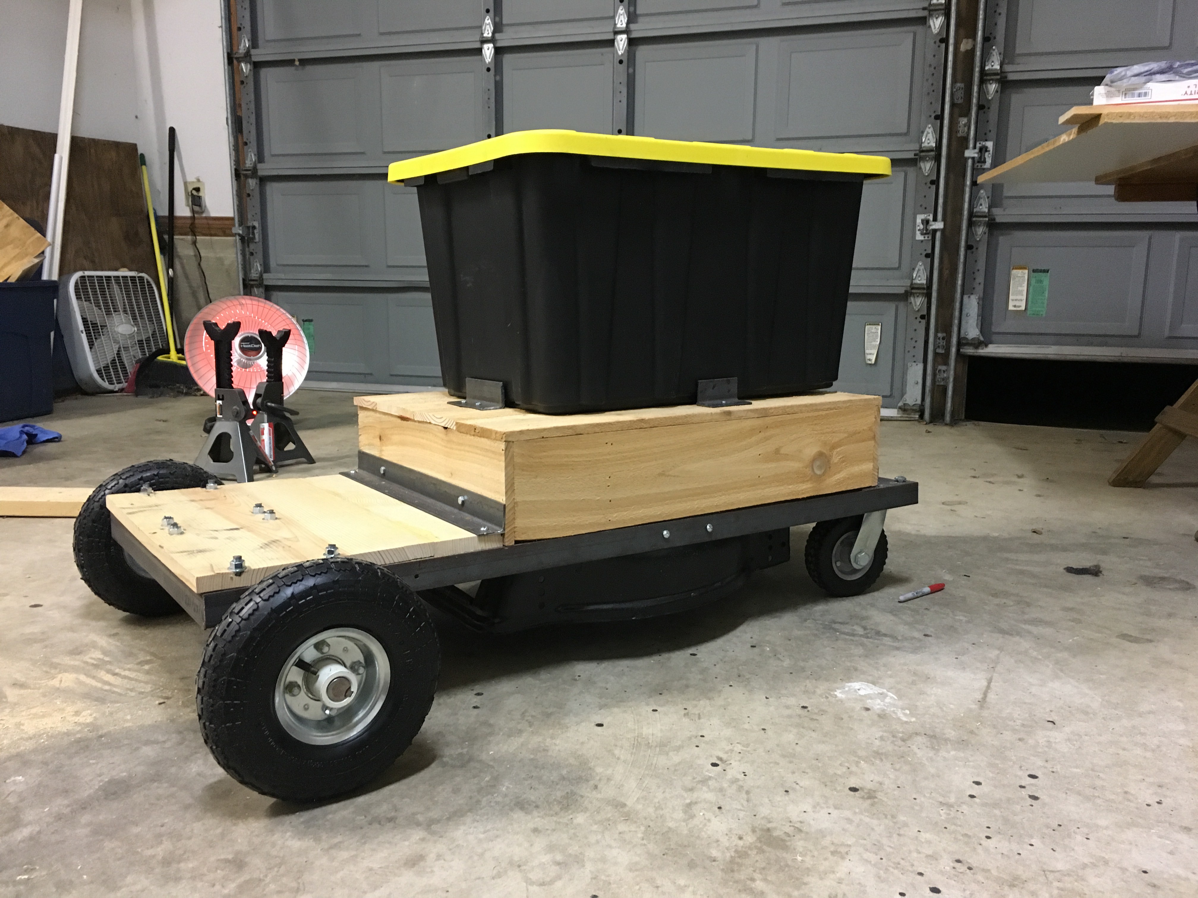
01/12/2018 at 16:08 • 0 commentsAfter putting the valve and various PVC fittings together I noticed that the sprinkler bar was well below the wheel well. After measuring, I determined that the bin and plumbing assembly had to be lifted about 6 inches. I didn't want to add that much weight to the bot so I constructed the platform to lift the bin out of fence boards ( 1"x6"x6"). The fence boards are extremely light and durable, readily available and are reasonably priced. Once the platform was constructed I cut a whole for the plumbing and installed small pieces of angle iron braces to hold the bin in place.
![]()
-
Water Delivery Mechanism
01/11/2018 at 14:40 • 0 commentsSince this project is all about watering the lawn, I thought it would be a good idea to see how well a gravity fed system would work. In order to perform a truly empirical test, I decided to test the water flow independent of the bot. I plumbed the storage container (i.e. plastic storage bin) to the valve, that will be driven by a relay in the final bot construction, to the sprinkler t-bar. I was surprised that the pressure and flow with a full tank of water was almost identical to the last inch of water. While the tank was draining I started a timer to determine how much of the lawn could be covered within 'x' amount of time. It drained 40 gallons in about 40 minutes, so around 1 gallon in a minute. Of course, I don't know how fast the bot can move so the coverage is still an incalculable value but were getting closer.
Here is a video of the water flow :
-
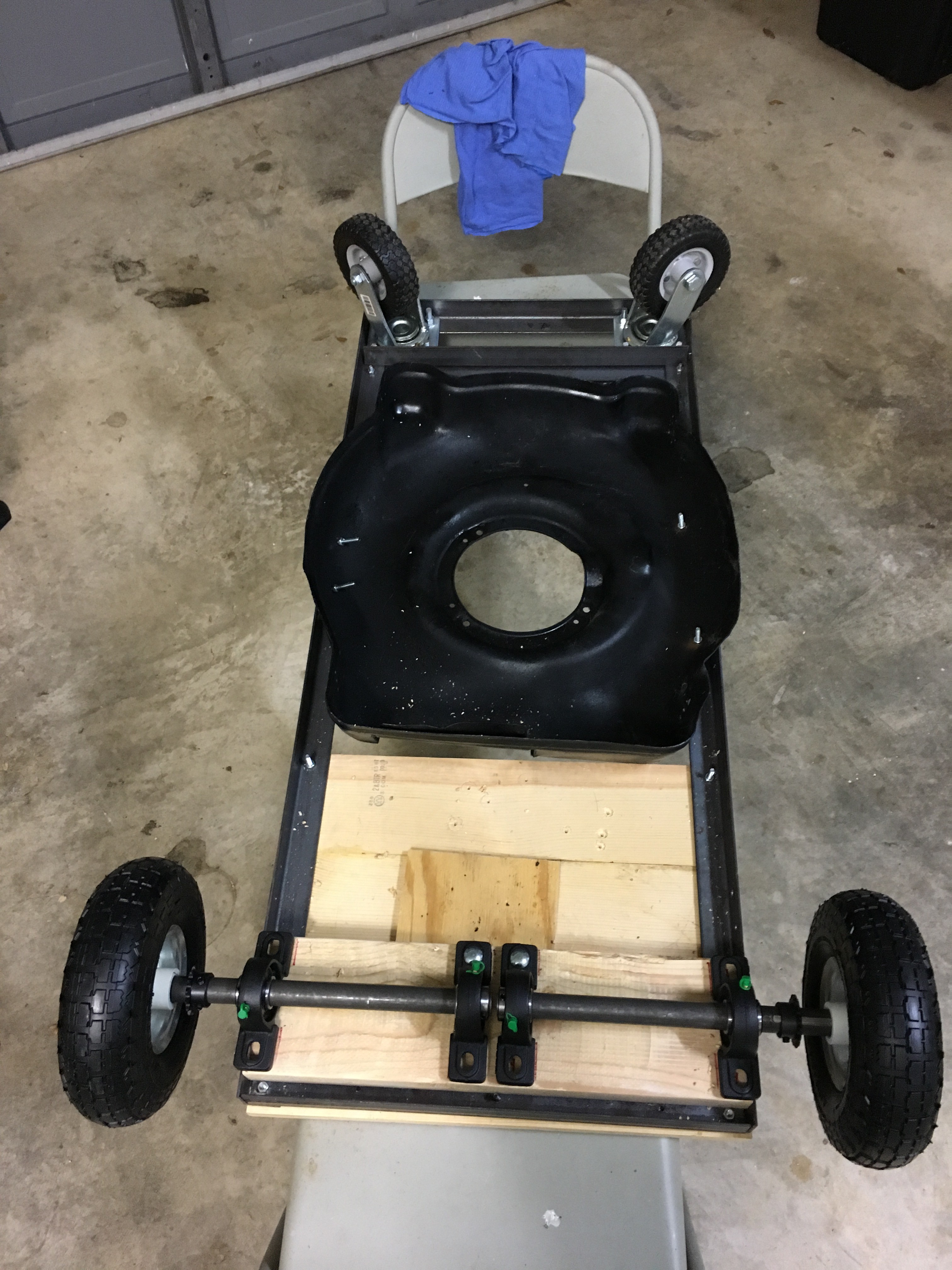
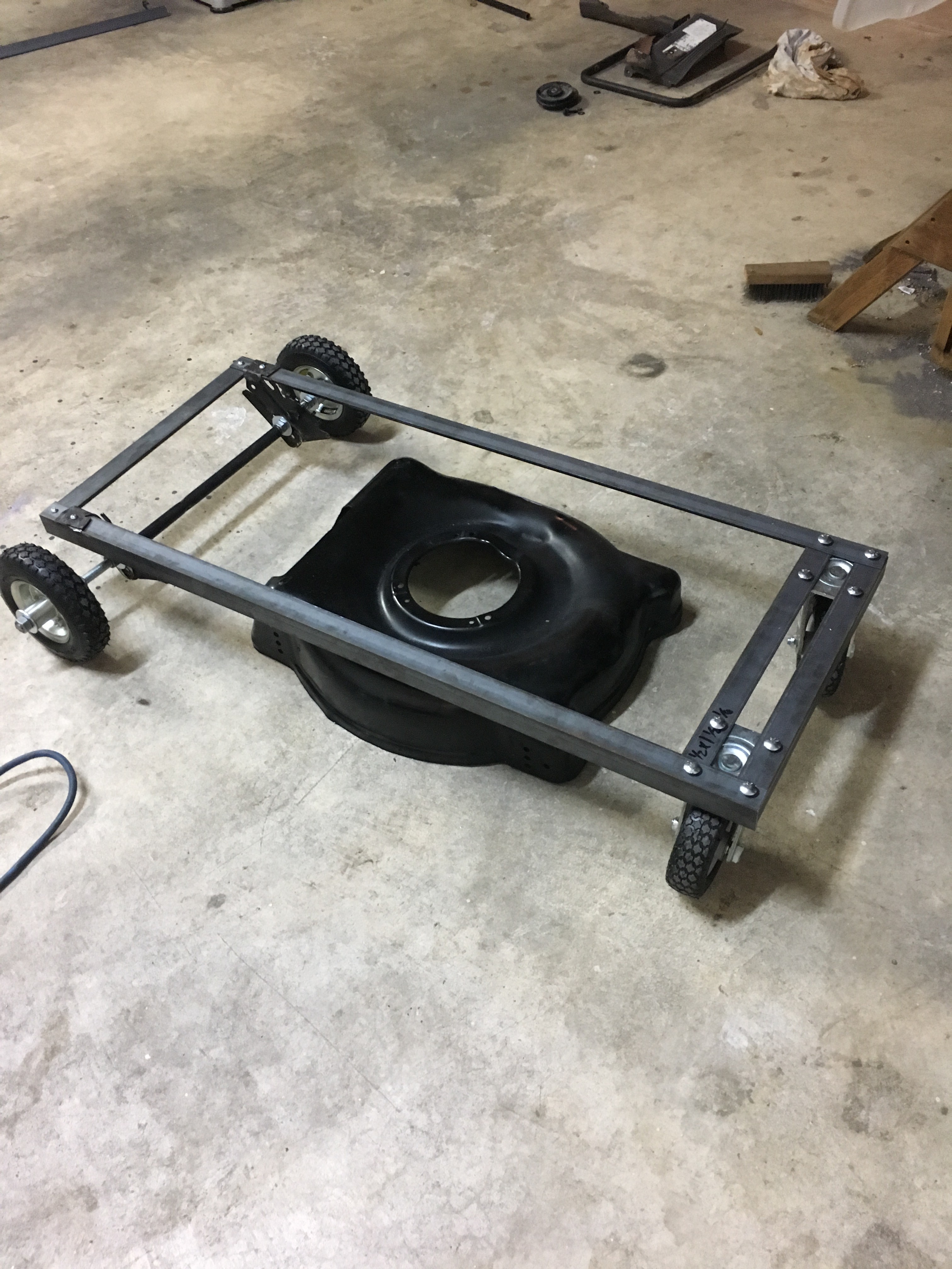
Split Axle Installed
01/09/2018 at 21:02 • 0 commentsTonight I mounted a split axle onto the base of the bot for easy maneuvering. The wheels are slightly bigger than the front wheels, thanks to the suggestion given by [dohabandit] in the comments. The gears for turning the wheels are also secured to the axle via a key and hex screw. Eventually, the gear on the axle will attach to the motor and be able to move independently for better turning and more finite control.
![]()
-
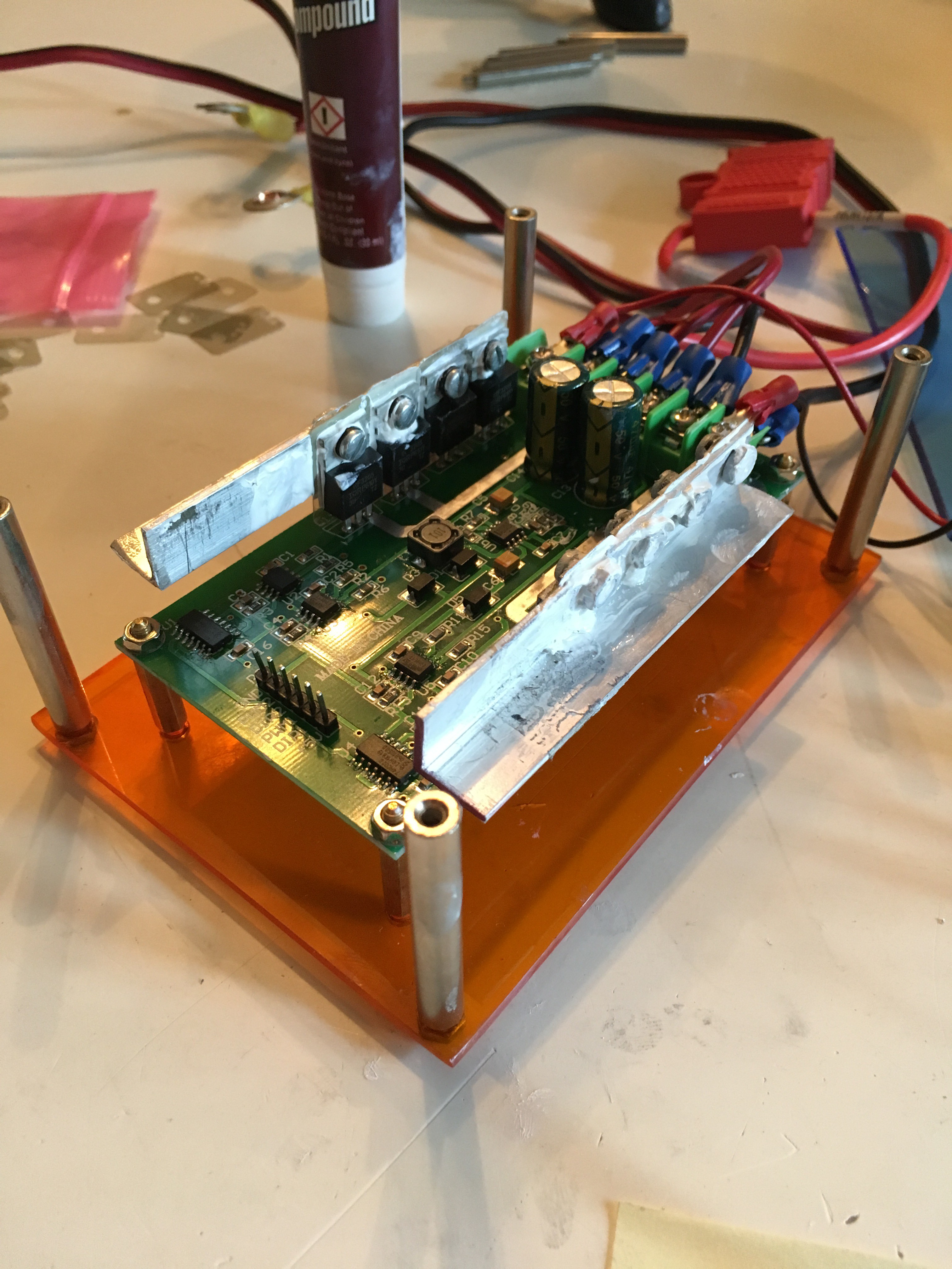
Custom Heat Sink for H-Bridge
07/28/2017 at 11:56 • 0 commentsAs I mentioned in the previous post, the FET's on the H-Bridge got ridiculously hot after a very short amount of time. To rectify this, I constructed a heat sink out of angle aluminum and a lot of thermal paste. Since the heat sync spans all of the FET's I made sure to put rubber gaskets and insulation on the FET's themselves in order to prevent an electrical short.
![]()
-
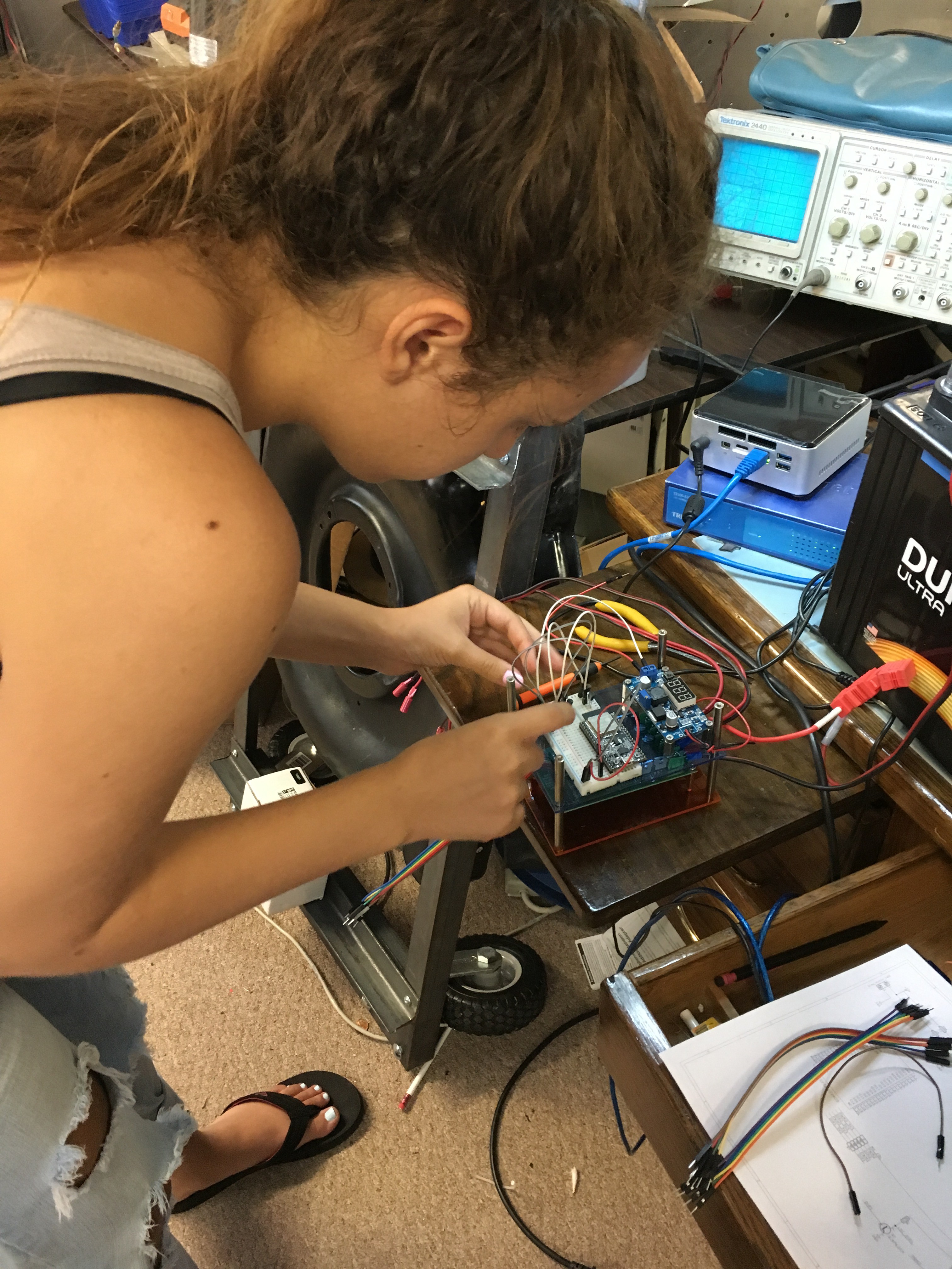
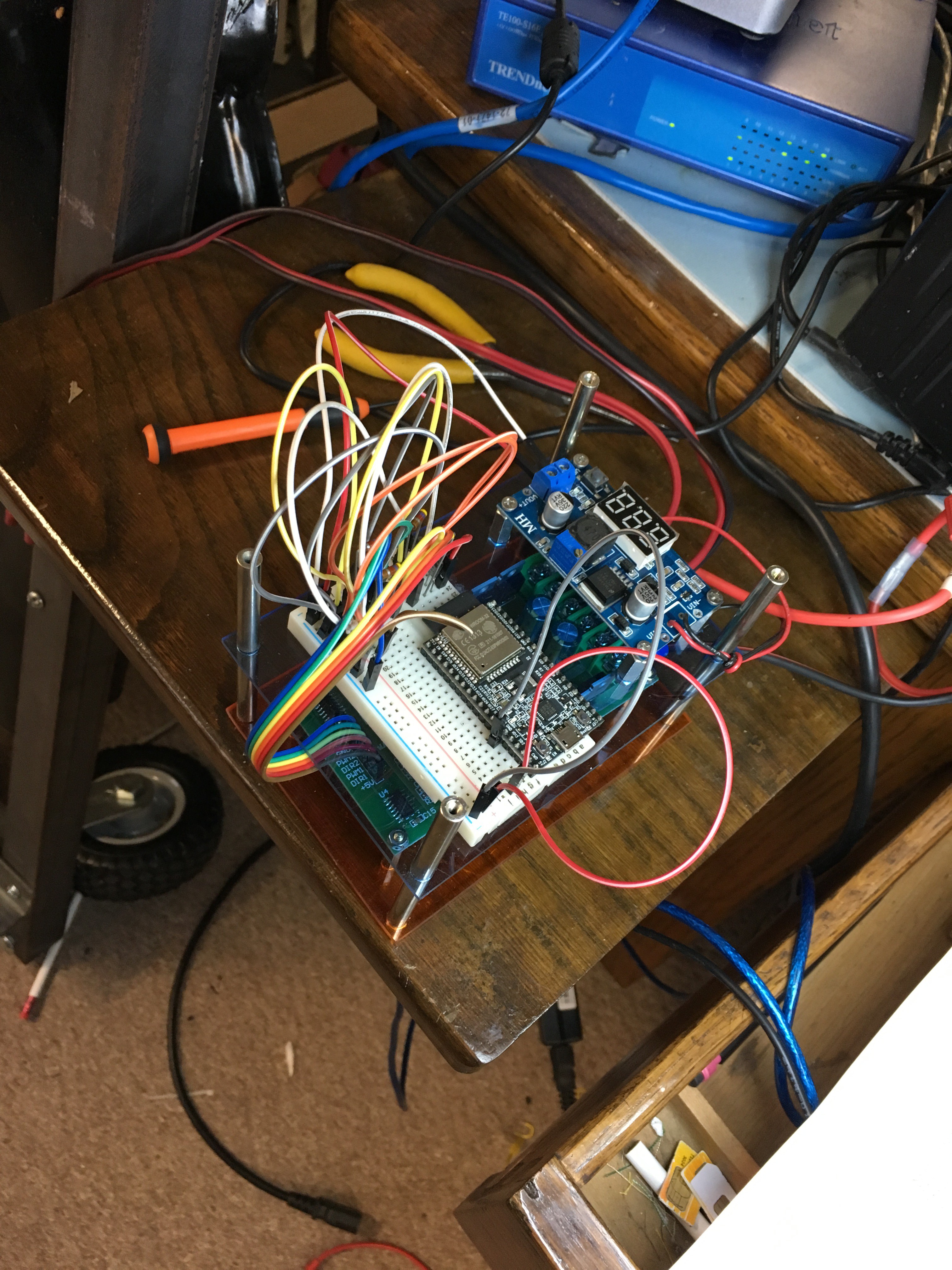
Building the Circuit and Unforseen Issues
07/25/2017 at 14:02 • 0 commentsBuilding the circuit was pretty straight forward. I uploaded the Kicad schematic for anyone that is interested. This part of the build did uncover some unforeseen issues. The H-Bridge manual was completely written in Chinese, so I scoured the internet for information. I thought I had a good understanding of the bridge until the FET's became insanely hot during brief testing. Of course it goes without saying that buying some thermal paste and constructing a heat sink are in my immediate future. In addition, the solenoid for the water valve pulls 12v and 2 amps ! I don't want to drain my battery on a water valve so I will need to drive the power with a relay. Since each wheel needs to move independent, I need the sprockets mounted to the tire to transfer the force. However, the sprockets for the tires are not easily mounted to the tires. Mainly because the size of the sprockets in relation to any mountable surface.
Here is some photos of the circuit prototyping:
![]()
![]()
-
Frame Complete
07/05/2017 at 12:52 • 0 commentsThe frame is looking pretty solid now. I think I am going to switch gears now and start writing the code for the esp 32 micro controller. Once I have the circuit and the code working, I will start mounting the motors, sprinkler system, batteries, etc.
![]()
-
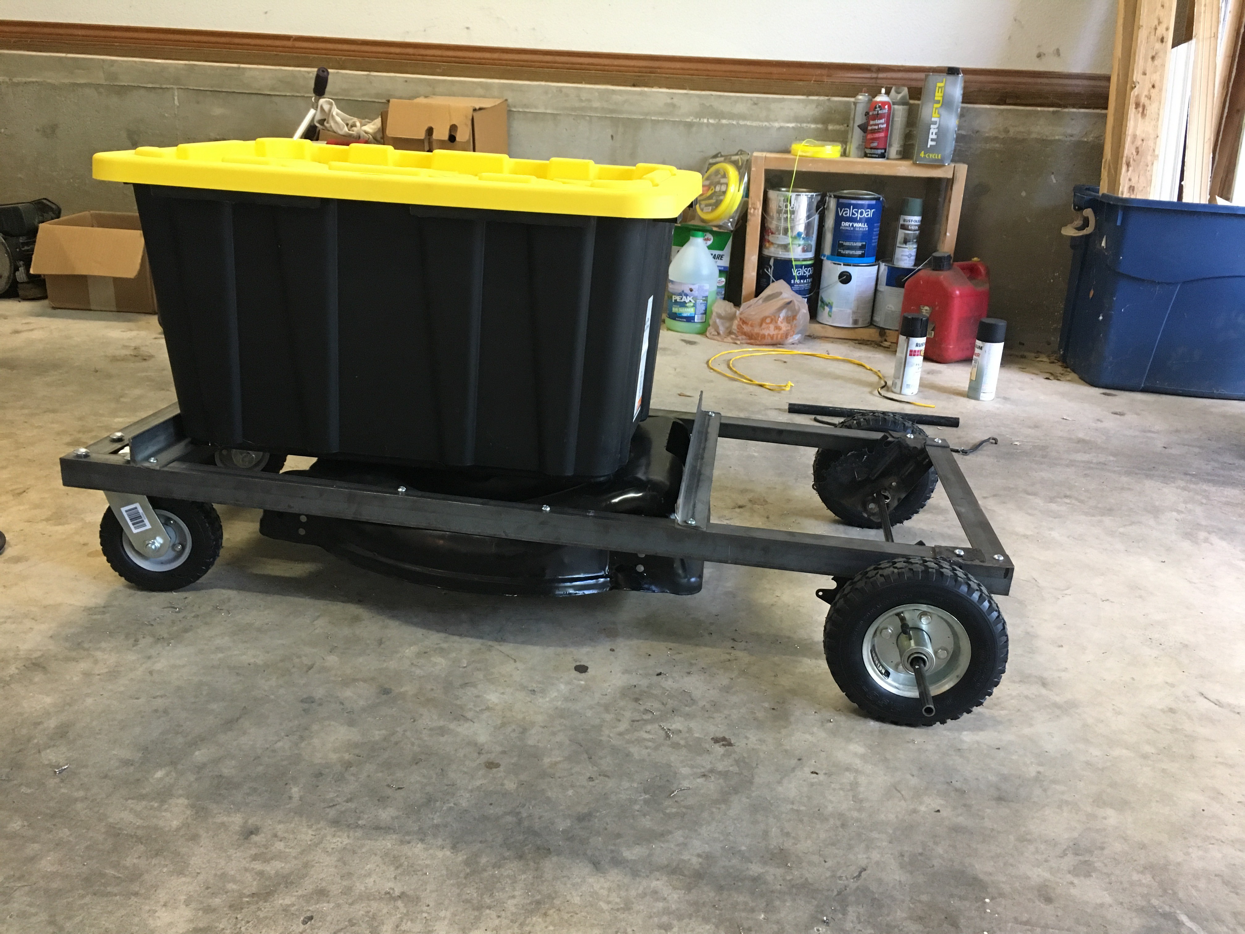
Weight Test
07/03/2017 at 17:45 • 0 commentsWanted to see if the bot could hold weight since the end goal is to carry a fair amount of water, plumbing, electronics, batteries, motors, etc.. Not to mention it was pretty fun ;)
-
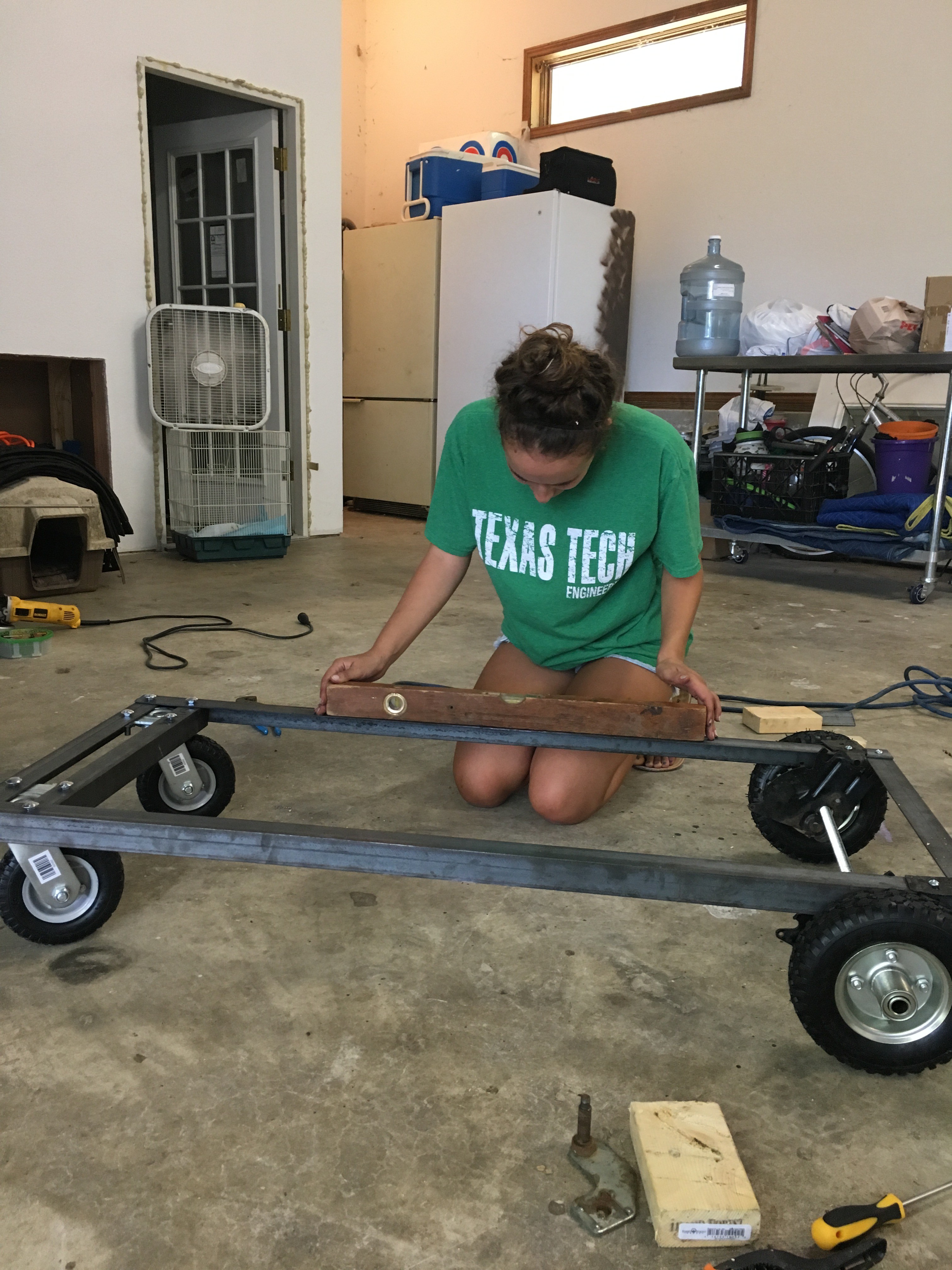
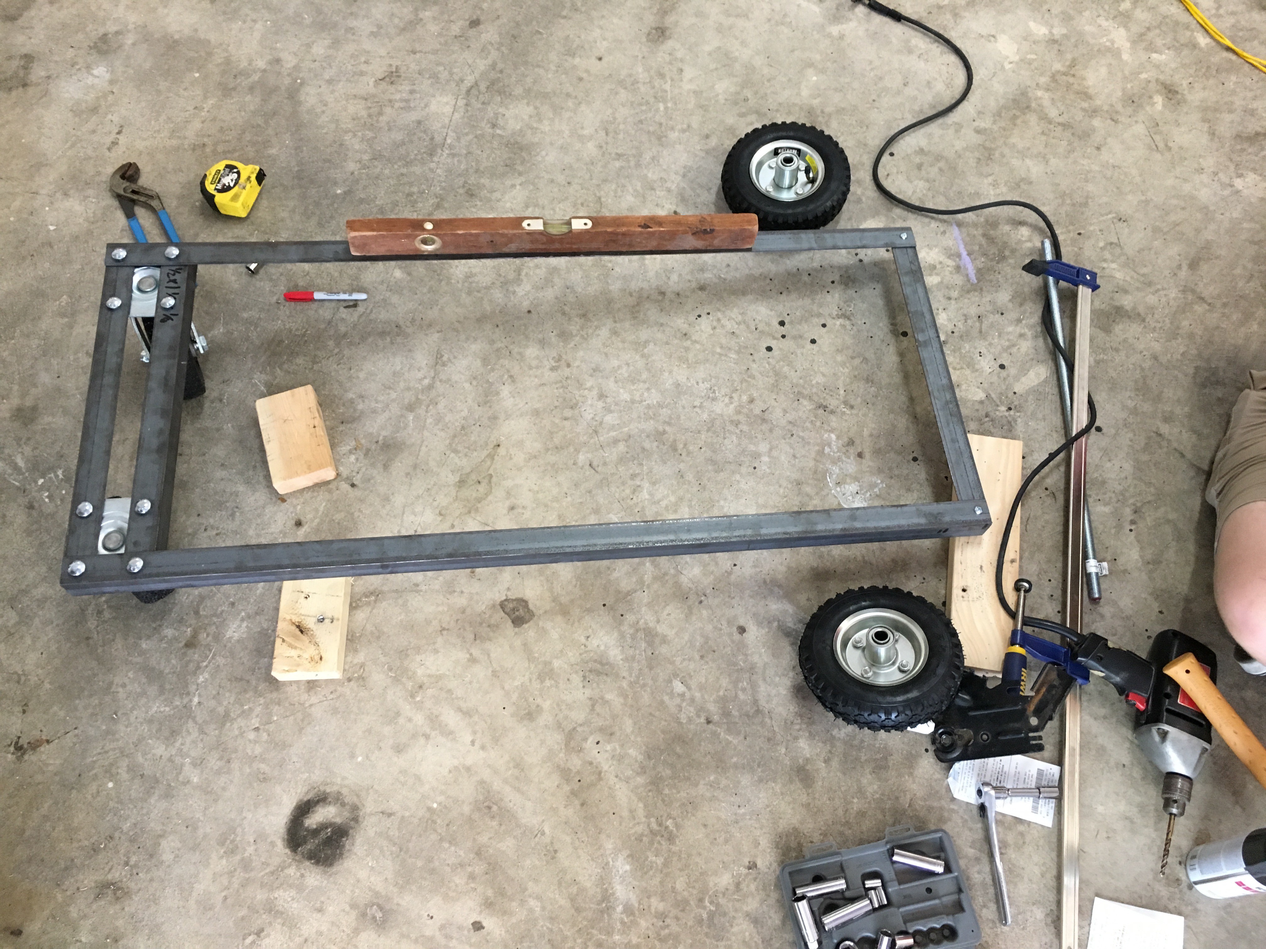
Starting the Mechanical Build
07/03/2017 at 17:38 • 0 commentsStarted the mechanical build for the waterbot, fun to actually see it coming to fruition.
![]()
![]()
![]()
-
Wrote a iPhone App to Control the Robot
06/27/2017 at 17:01 • 0 commentsI am still waiting for my components to come in, so I decided to write the app to interact with the ESP32. I will be using the app to test my code and to eventually drive the bot. Currently it is on my own private network but eventually I can add a dyndns address to control it remotely.
-
Calculating the Speed with a 50 gallon Reservoir
06/23/2017 at 15:30 • 0 commentsWhile I am waiting on my components, thought I would do the math to figure out how fast the bot would travel carrying 50 gallons of water (400 lbs) in a reservoir.
Wheel size: 6 inches diameter.
Wheel size sprocket:3 inches OD.
Motor size sprocket:2 inches OD.
Reduction ratio: 1.5 to 1
Target water weight: 400 lbs (50 gallons)
Torque rating of the (50rpm) motor = 8ft-lbs.
Torque to drive the wheel: 8 ft-lbs x 1.5 = 12 ft-lbs.
Convert units from ft-lbs to in-lbs: 12 ft-lbs x 12 = 144 in-lbs.
Convert to force: 144 in-lbs / 3 in = 48 force lbs
48 lbs force: traction of one wheel
Maximum traction for two wheels: 48 lbs force x 2 = 96 lbs force
96 lbs force = 427 N (Newton)
6 in = 0.152 meter
400 lbs = 181 kg.
427 N = 181 kg x a and a = 2.36 m/sec^2
50rpm / 1.5 = 33.3rpm = 0.556 rev/second
0.556 rev/second x 6 in x Pi = 10.5 inch/second = 0.267 m/s (final speed).
2.36 m/sec^2 = (0.267 m/s - 0 m/s) /0.11 s
Conclusion:
400 lbs robot should be able to move from static to 10.5 inch/second in just 0.11 second.
** Probably slower because I didn’t account for debris / rubble on the ground, uneven surface, etc … also, climbing a slope may create issues as well.
Of course, 50 gallons is the end goal. For the initial build the reservoir will contain only 35 gallons of water ( 280 lbs )