 ziggurat29
In this iteration of the demodulator for the RedEye protocol, I am using a module intended for IrDA, which operates at 4800 up to 115,200 bps and is baseband -- i.e. a '1' is indicated by 'light off' and a '0' indicated by 'light on'. (OK, that's not strictly true: the '0' is actually a blip that is 3/16 the full bit period, but that's about the only difference from just hooking the led straight to the uart). So it should easily be able to detect the 32 HKz RedEye carrier.
This implies that the ISR will now be triggered on each on each pulse received -- all 32,768/sec of them -- rather than the envelope as is the case with the Vishay TSOP device. But the BluePill can easily handle that.
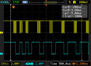
I implemented a new state machine. It used the same resources as the TSOP decoder, even with the same configuration (a timer clocked at 2x carrier frequency to serve as a one-shot), so that was handy. The one-shot is set to 2/3 a half-bit which counting pulses for the 'burst' of 6-8 pulses as per protocol, or a 1/2 bit when expecting quiescence. So it works as a series of 'expectations', the three half-bit sync pulses, and the rest are half bit pairs of 0-1 or 1-0. Deviations from the expected sequence (including pulse count) reset the machine.
This seemed to work reliably and recover from errors at the byte level. (I.e. a damaged byte would not preclude syncing up correctly on the next incoming byte.)
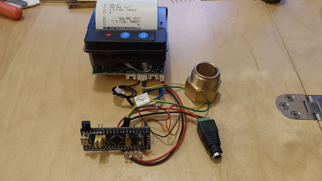
I wound up making a 'better' module using some stranded 30 AWG and crimped Dupont connectors with some free-wired circuitry for the support components, along with some UV-curable resin for some stress relief.

This was fiddly to build, but it got me off the breadboard.
I did also implement the error-correction capability using the 4 parity bits, which can correct single bit errors, and I tested this by deliberately damaging bits. However this does not seem useful to me because the demodulator will kick out bad signal before there is a chance to correct it. So maybe a different implementation that continues to try to receive despite obvious signal errors might enable the use of the parity correct feature. I'm still skeptical because you can only correct single bit errors, which is a very short period of time. I suspect most signal problems are gross in nature, like blockage for far longer than a single bit period. Also there is not a means of knowing if the bit error is in the data, or in the parity. Why should we consider the parity bits as authoritative and the data bits as less trustworthy? So a conundrum.
I did get transmitting working as well, and tested sending to a physical HP 82240B printer. I also tested sending to a second interface board, which was kinda cool in itself.
So this then stimulated some more features, exploding the space of my flash.
I did add a capability to send the received IR over the USB-CDC or UART1. The 'monitor' is usually on USB-CDC, so if you send the IR there, then that precludes the monitor. So I added an 'escape' of "+++" (in Hayes AT tradition) to get back to the monitor so you can do things like change settings.
This only works, though, in that one side of the half-duplex USB CDC is the received IR data, and the other remains the monitor. So you can type commands blind even in the IR data mode (you have to, to be able to send the +++ escape sequence). But this precludes sending IR data.
So I need to put my product manager hat on for a bit to think some more on that. Because I would like the interface to also fully support being a two-way RedEye USB adaptor module. I can send now via the 'send' command I implemented, but that's not the same as what a 'proper' adapter would do. A 'proper' adapter would present as a USB-CDC serial, and then merrily transceive RedEye data. The code is all there to do that, but it would preclude the monitor function for doing setup. The monitor can be put on UART1 -- that is supported now, and it's helpful for development -- but I'd rather not require another connection to the board. This board has no existing buttons that could be used to enter the monitor mode and exit from it.
Oh well, at some point things become a separate project. Most of that capability is present in this firmware, you can make a one-way adapter. It would be straightforward to make a separate project focused just on the two-way adapter-ness of it.
In the meantime, I packed up this build and send it on to my friend who wants to print from his calculator.
But now that I've got an IrDA module hooked up, I feel the urge to do some actual IrDA. And that is a separate project.
Discussions
Become a Hackaday.io Member
Create an account to leave a comment. Already have an account? Log In.