 ziggurat29
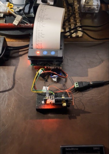
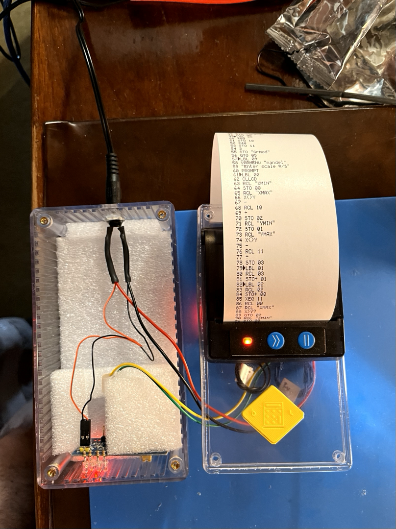
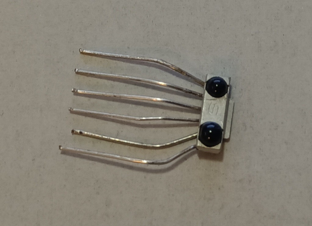
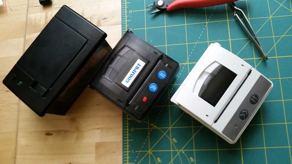
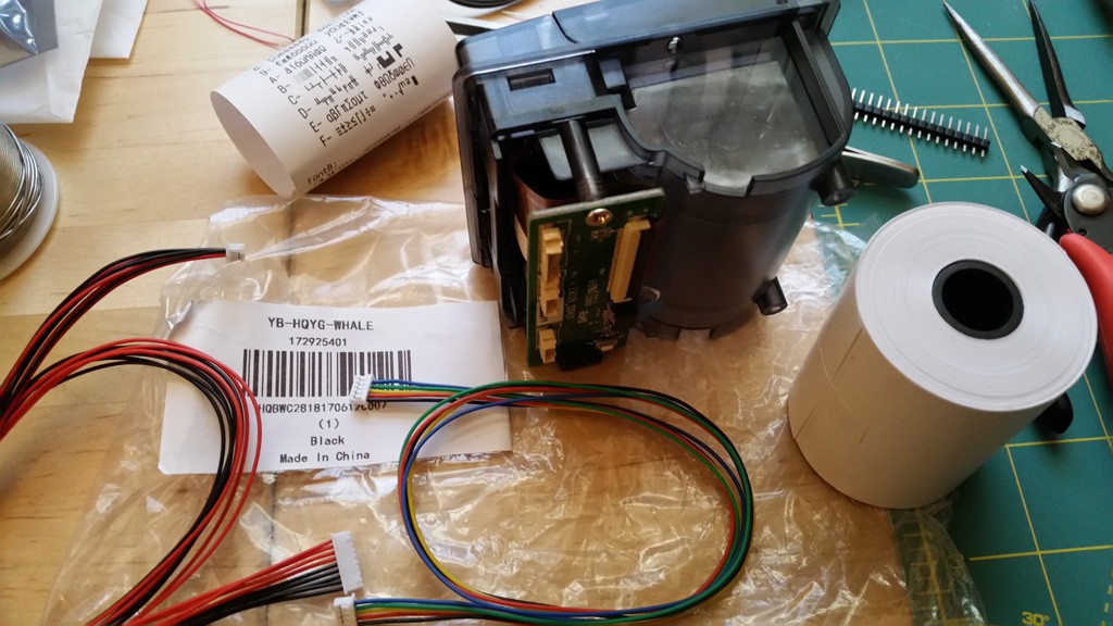
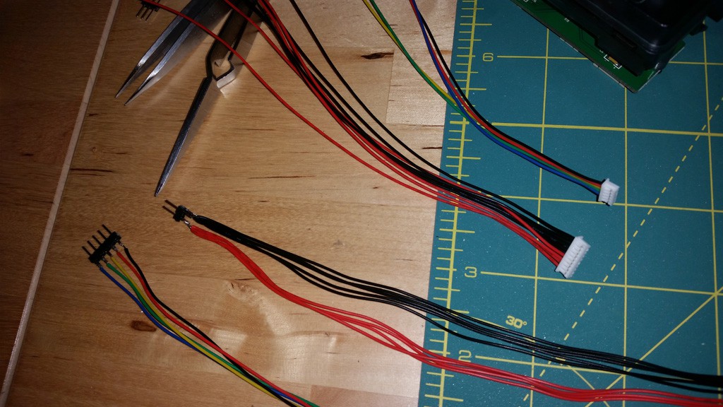
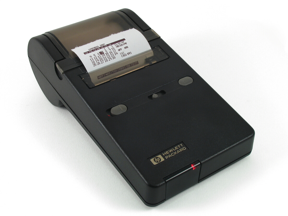
Many folks that use HP calculators of yore like to be able to use the infrared printer. These printers are long since out-of-production, and really expensive given what they are, and some folks in a separate forum wondered if a workalike could be crafted from cheap receipt printer cores. So I went about doing so using an also-cheap BluePill cpu board and IR detector module intended for TV remotes. (It can also work with detector modules intended for IrDA applications.)
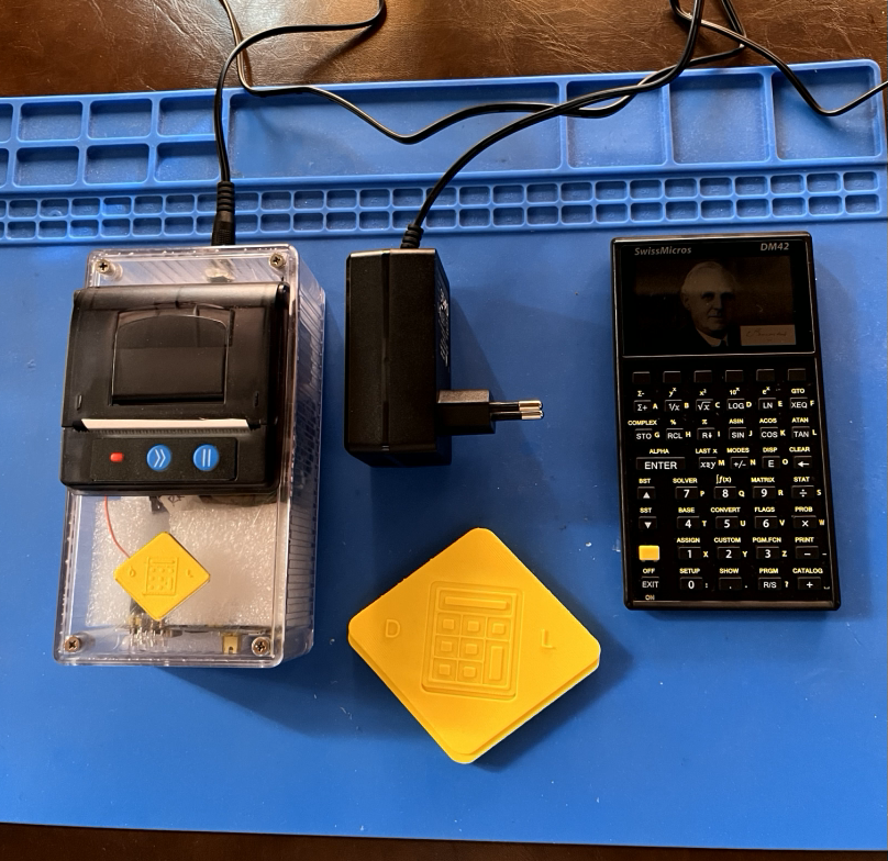
The core components will total about USD $30 as described here, and case will add something to that should you go for such, as will power adapter.
The interface board can also be used without a printer as a USB adapter, so you can 'print' to some receiving application running on your computer.
I have tested it with my 28C and others have tested it with their DM42.


 Ben Hencke
 glgorman
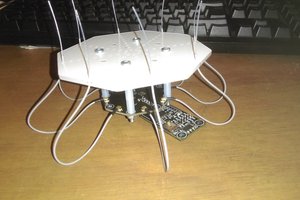
 Charlie Smith
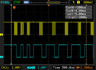
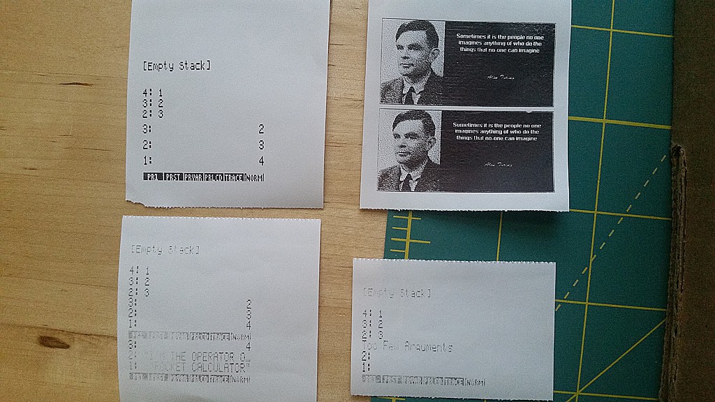
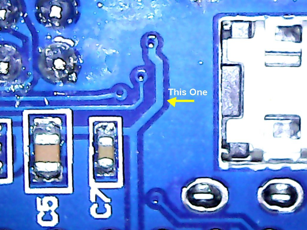
Excellent work! The description of how you overcame the faulty demodulated output of the IR receiver was stupendous. Especially since I'd just been reading on HP forums that the TSOP4133 "won't work" due a lengthy minimum post-burst period. Your writing is fun too!