ziggurat29
-
Success in the Field
4 days ago • 0 commentsRecently, I was contacted by [hpsoftek65] asking for a printer interface to enable printing from a Swiss Micros DM42 calculator. It does support IR printing as with the original, but as printers are hard-to-find [hpsoftek65] reached out asking for an assembled unit.
It took a little while for the printer core to arrive from China, but I did test it all out and sent the un-cased unit off to Italy. It's a pity that shipping cost nearly as much as the parts! I guess that's just the way it is. [hpsoftek65] is a better photographer than me, and I was granted permission to share some clips of the functioning unit.
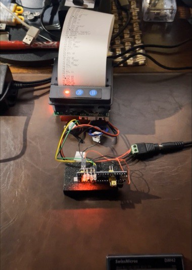
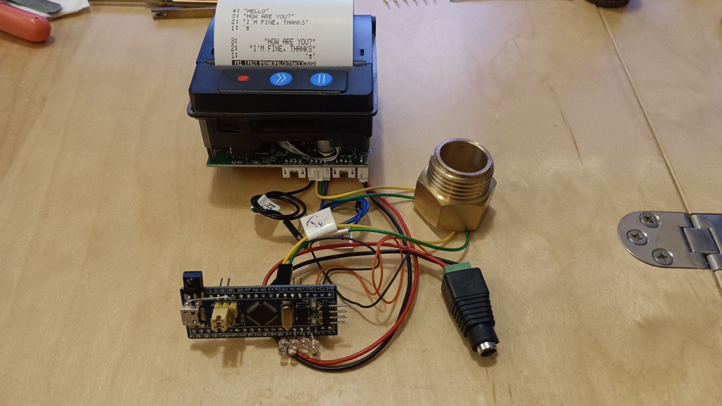
What I sent was the wired components -- no case. Out-of-box it was tested it successfully:
![]()
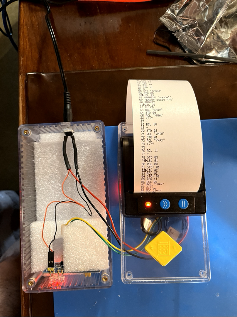
Then had to wait for a simple box to arrive to produce a case. Semi-assembled:
![]()
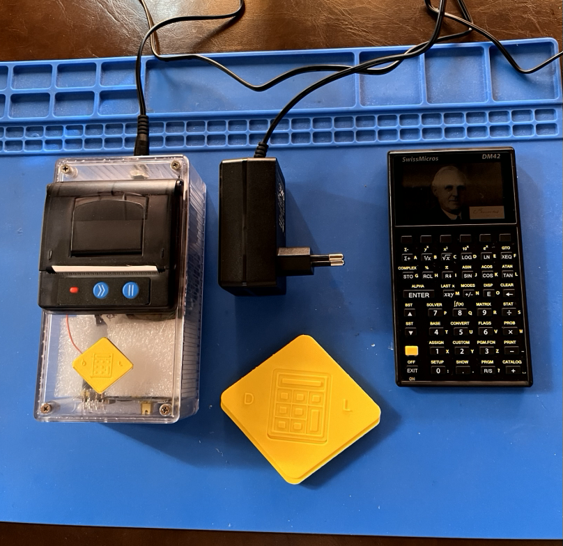
And all closed up ready to test:
![]()
And here it is in action:
Noticeable things:
Printing speed is pretty slow. This is partially because that's the way the sender (the calculator) is sending it out. The link is one-way, and it is advised to send lines no faster than the printer can print lest the buffer overflow. The original printer could take 1.2 - 1.8 sec to print a line (depending on battery state), so the calculators sent them out slowly. I haven't measured the speed of this particular printer.
The IR data transfer rate is 78 by/sec, and for text there is 25 char/line, so maximally 3 line/sec. However in this case the lines are always converted to bitmaps in order to support the distinctive HP82440B character set, and a 'line' of graphics takes about 1,000 bytes. These printers usually operate at 9600 bps, so that means each line is again about 1 sec to transfer the data to print. So it winds up being about the same as the original printer. (The printers can often be configured to transfer faster than 9600 bps, though how to do that is model-specific.)
The range is short as well. The interface board can support a much greater range -- the receiver module is designed for TV remote control applications. It's more a function of how bright the emitter is. Some suggest that the range is deliberately limited to thwart cheating in classroom environment, though this seems less likely than the more straightforward explanation of saving battery. The DM42 which I have seen has a 100 ohm series dropping resistor, which is pretty high for pulsed IR. 15 ohm would not be unusual. But the calculator does run off a single CR2032, so a lot of printing would be a lot of draining. A bold owner could parallel a low value resistor and possibly eek out a little more range.
Anyway, it's always satisfying to see the project in the field working for someone else!
-
IrDA [Explosive Space] Demodulator
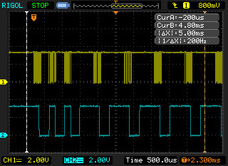
02/15/2025 at 14:43 • 0 commentsIn this iteration of the demodulator for the RedEye protocol, I am using a module intended for IrDA, which operates at 4800 up to 115,200 bps and is baseband -- i.e. a '1' is indicated by 'light off' and a '0' indicated by 'light on'. (OK, that's not strictly true: the '0' is actually a blip that is 3/16 the full bit period, but that's about the only difference from just hooking the led straight to the uart). So it should easily be able to detect the 32 HKz RedEye carrier.
This implies that the ISR will now be triggered on each on each pulse received -- all 32,768/sec of them -- rather than the envelope as is the case with the Vishay TSOP device. But the BluePill can easily handle that.
![]()
I implemented a new state machine. It used the same resources as the TSOP decoder, even with the same configuration (a timer clocked at 2x carrier frequency to serve as a one-shot), so that was handy. The one-shot is set to 2/3 a half-bit which counting pulses for the 'burst' of 6-8 pulses as per protocol, or a 1/2 bit when expecting quiescence. So it works as a series of 'expectations', the three half-bit sync pulses, and the rest are half bit pairs of 0-1 or 1-0. Deviations from the expected sequence (including pulse count) reset the machine.
This seemed to work reliably and recover from errors at the byte level. (I.e. a damaged byte would not preclude syncing up correctly on the next incoming byte.)
I wound up making a 'better' module using some stranded 30 AWG and crimped Dupont connectors with some free-wired circuitry for the support components, along with some UV-curable resin for some stress relief.
![]()
This was fiddly to build, but it got me off the breadboard.
I did also implement the error-correction capability using the 4 parity bits, which can correct single bit errors, and I tested this by deliberately damaging bits. However this does not seem useful to me because the demodulator will kick out bad signal before there is a chance to correct it. So maybe a different implementation that continues to try to receive despite obvious signal errors might enable the use of the parity correct feature. I'm still skeptical because you can only correct single bit errors, which is a very short period of time. I suspect most signal problems are gross in nature, like blockage for far longer than a single bit period. Also there is not a means of knowing if the bit error is in the data, or in the parity. Why should we consider the parity bits as authoritative and the data bits as less trustworthy? So a conundrum.
I did get transmitting working as well, and tested sending to a physical HP 82240B printer. I also tested sending to a second interface board, which was kinda cool in itself.
So this then stimulated some more features, exploding the space of my flash.
I did add a capability to send the received IR over the USB-CDC or UART1. The 'monitor' is usually on USB-CDC, so if you send the IR there, then that precludes the monitor. So I added an 'escape' of "+++" (in Hayes AT tradition) to get back to the monitor so you can do things like change settings.
This only works, though, in that one side of the half-duplex USB CDC is the received IR data, and the other remains the monitor. So you can type commands blind even in the IR data mode (you have to, to be able to send the +++ escape sequence). But this precludes sending IR data.
So I need to put my product manager hat on for a bit to think some more on that. Because I would like the interface to also fully support being a two-way RedEye USB adaptor module. I can send now via the 'send' command I implemented, but that's not the same as what a 'proper' adapter would do. A 'proper' adapter would present as a USB-CDC serial, and then merrily transceive RedEye data. The code is all there to do that, but it would preclude the monitor function for doing setup. The monitor can be put on UART1 -- that is supported now, and it's helpful for development -- but I'd rather not require another connection to the board. This board has no existing buttons that could be used to enter the monitor mode and exit from it.
Oh well, at some point things become a separate project. Most of that capability is present in this firmware, you can make a one-way adapter. It would be straightforward to make a separate project focused just on the two-way adapter-ness of it.
In the meantime, I packed up this build and send it on to my friend who wants to print from his calculator.
![]()
But now that I've got an IrDA module hooked up, I feel the urge to do some actual IrDA. And that is a separate project.
-
...but is anything really ever 'done'?
02/12/2025 at 14:40 • 0 commentsNo, it's not. A few weeks ago a gentleman asked about procuring a completed printer interface. It's been some 7 years since I did this project, so I had to refresh my memory.
I recall being concerned about using the TSOP4133 in this application. It has worked fine for me with my calculators, but I am pushing it to the limits of the specification, so notionally it could be problematic with a different calculator or different batches of TSOP's. I had dealt with the fringe cases in software, but I was still wanting a more confidently robust alternative. I planned to implement a new demodulator based on an IrDA module, which should definitely work with the signaling. The code will be different, since modulated data will be received (the TSOP demodulates with envelope detection, but we'll receive the individual bursts here). The 32 kHz carrier can easily be handled as as a direct interrupt source since the BluePill is running at 72 MHz.
Along the way, I discovered that a feature I thought I had implemented was not: the ability to use the interface board standalone (i.e. no printer) as an HP-IR-to-USB adapter. The gist being that instead of directing the IR to the printer rasterizer, instead send it to the USB-CDC serial port. So I needed to code that.
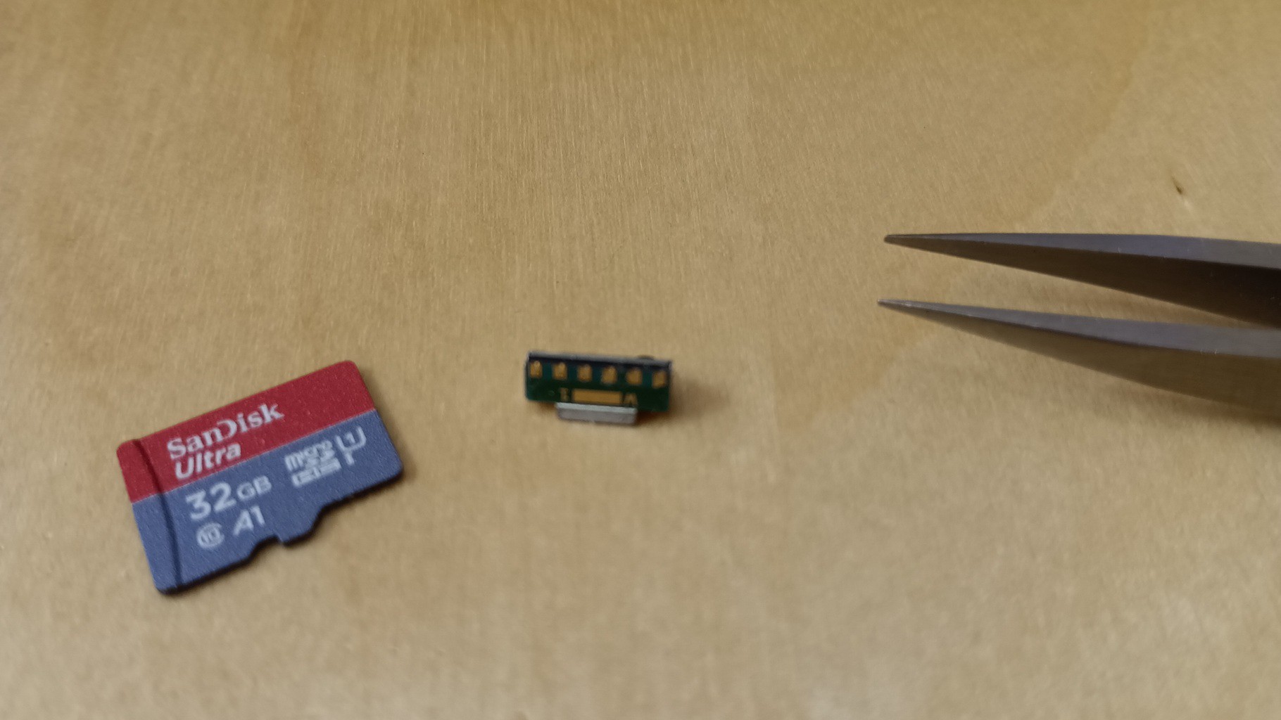
I had started this back in 2018, but I apparently damaged my IrDA module -- possibly spending too long soldering to the tiny device. I had recently picked up some other IrDA modules that were surplus from Electronic Goldmine -- the Sharp GP2W0004-YP. So tiny!
![]()
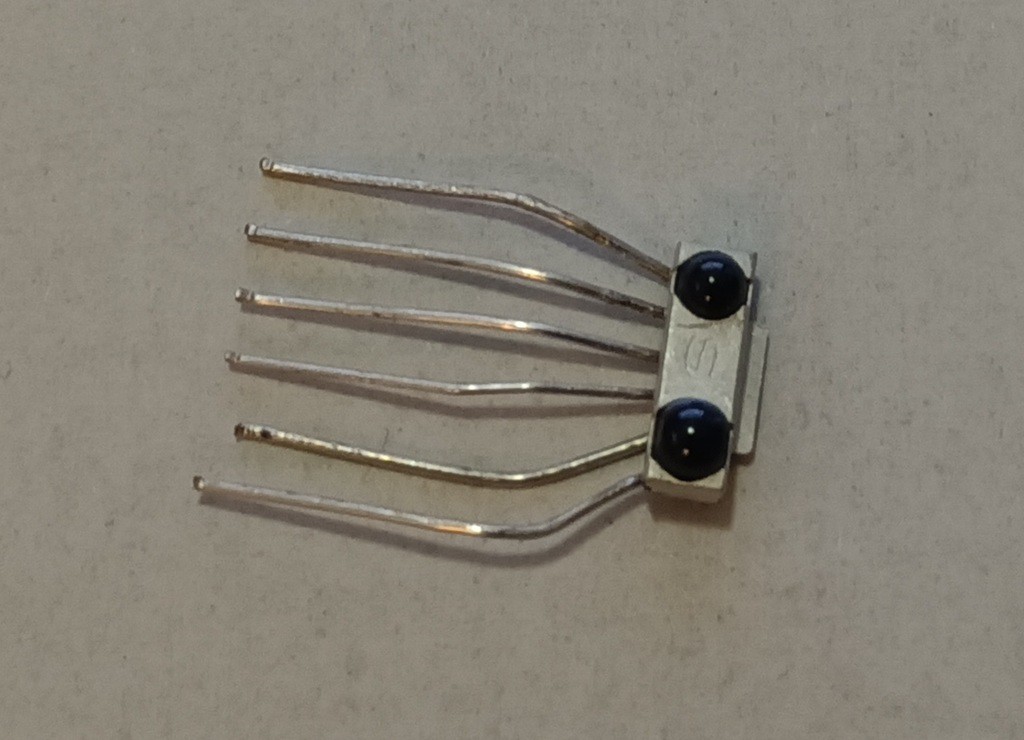
However an idea struck me to solder on some rigid wire (lead clippings from resistors) in a dispersive fan pattern, and subsequently bend them parallel to a 0.1" pitch. Then the SMD device becomes breadboard-friendly.
![]()
I'm not using these for actual IrDA here, but I decided to hook them to pins that could be configured to a serial port so that I can fiddle with IrDA later (for a different project). Here those lines will be configured as an external interrupt source for the RX signal, and a PWM for the TX signal though it is not relevant in this case. Or is it? I mean, I've now got an emitter for free, maybe I should also support sending HP IR signals? It's not meaningful for the original printer use-case, but might be interesting in the alternative adapter use-case.
That particular pin when not for UART can work off timer 2 channel 3 in PWM mode. So I can configure the TIM2 for 32768 Hz, 50% PWM, and gate the signal. I was previously using TIM2 as the system tick, so I moved that to TIM3. I use TIM1 as the bit clock. Actually, it's 1/4 bit clock, because the bursts are 1/4 a bit period.
The signaling scheme is a kind of 'biphase-level' signal where each bit has a burst in either the first or second half of the bit time (the burst lasts a quarter of the bit time). If the burst is in the first half, it is a '1', and if it is in the second, it is a '0'. There are 12 bits transferred (4 parity and 8 data) and 6 half-bits for framing (three for sync and three for stop). So a total of 15 full bit times.
In the interest of simplicity, I encode these 15 bits as 30 half-bits representing the burst/no-burst state for each half bit period. In this way, the machine (operating at 4x the bit timing) clocks out the encoded bits in two phases: phase0 conditionally turns on the signal to start a burst if the encoded bit is '1', and phase1 unconditionally turns off the signal. This this encoded-bit-clock is a multiple of the carrier frequency, it is possible to make a picture-perfect output waveform. This fits in a 32-bit word and has two spare bits which I use as a sentinel for end-of-frame.
Short story: encode a byte by setting sync bits, computing parity, and appending data and stop bits. Then set to phase0 and start the (quarter) bit clock. In phase0, test the high bit and start a burst if it's '1', then transition to phase1. In phase1 turn off the burst and shift the bit stream up. If it's the terminating sentinel, turn off the bit clock and we're done, otherwise set to phase1. Straightforward.
Demodulation was more involved. The existing decoder works with envelope-detected signal from the TSOP and decodes that based on the timing of transitions. In this case I will have the raw signal -- not the envelope. So my first idea was to layer on an envelope detector on top of the existing decoder. I did that seven years ago before I stopped working on it because I damaged my module. The work was ostensibly complete but not debugged. I had a bit of difficulty following my own code despite the comments, and anyway I had long since forgotten how the protocol works. So I started writing it afresh from first principles.
-
If You Can't Beat 'Em, Beat 'Em Into Submission
07/21/2017 at 02:34 • 0 commentsSummary:
A quirk of one of the printers, the APS EPM203-MRS, could not be disabled, but was worked-around.
This project is now functionally complete.
Deets:
Yesterday I had mentioned that one of my printers, the APS EPM203-MRS has a quirk whereby it gratuitously advances the paper before printing bitmaps. Moreover, it only does this sometimes, when there has not been prior output for 'a while'. This made my output look weird on that printer, and I don't like weird things. (OK, that's a general lie, but in this limited case, it's true.)
I scoured the manual looking for some way to turn off the paper advance feature/wart/whatever. Look as I may, and look as I might, there was no such feature found that night. I spoke 'the uncommon words of anguish', and retired for the night.
This morning I awoke to discover that I had turned into a giant cockroach. This situation only lasted a few minutes, but when it had ended I was left with a kooky idea: maybe I can just compensate for the paper advancing by doing a reverse paper feed before emitting the graphic. The sand in that vaseline is that the paper advance only happens /sometimes/, after there has been a period of output quiescence. If the data stream keeps coming to the printer with some reasonable pacing, no gratuitous paper feed is done. (Thank the maker for that little blessing -- really every horizontal line of pixels is it's own distinct graphic. It would be quite a mess if there was a paper feed between each horizontal line!)
So, sometimes, if you are faced with an inability to make things reliably the way you want them to be, you can as an alternative approach make them reliably the way you /don't/ want them to be. If I can make /every/ graphic output reliably have the unwanted paper feed, then I can reliably always do the workaround of the reverse paaper feed beforehand.
The approach I took wound up being a fairly surgical change:
- at then end of transmission of data to the printer, note the time, call it g_nLastTx. Initialize that to 0 at boot, btw. I'm just using the HAL_GetTick() which returns milliseconds since boot.
- before doing ouput, compute 'now' - 'then'. (I.e. HAL_GetTick() - g_nLastTx) 2s complement will make all your rollover worries better (mostly; more later). Call this difference 'duration'.
- if the 'duration' is longer than the safe amount of time to guarantee that the paper advance will happen, then sleep (via osDelay() in the CMSIS API) for the difference.
- now you should be guaranteed that doing a 'reverse paper feed' of a few pixels will counteract the gratuitous paper feed that you know the printer is going to insert.
OK, subtle detail on the timer rollover: we covered the usual case of 'I started just before the counter rolled over, and checked after it did, how do I handle that' with the unsigned 2s complement subtraction, but there is another issue when you rollover twice or more. Then the 2s complement doesn't help you. OK, the timer rollover will happen after 49 days, so you'd have to wait twice that time, so over 3 months of powered on but disuse before you'd be at risk of it. But I'm taking this thing to Jupiter and I can't have Hal telling me 'I'm sorry Dave, I can't open the pod bay doors until I get the output from your thermal printer.' and have to wait for 49/2=25 days while oxygen runs out. (Hal does love its petty torments.)
So I covered that scenario with a little hack. A 'haque', really -- it's not that dirty. The printer rasterizer process blocks waiting for a signal that a birmap is ready to be rasterized. That blocking has a timeout, which I arbitrarily set at 5 seconds. The intention of that is to let the thread awaken to realize that there hasn't been anything to do for a while, but that is nonetheless still alive, and it can just carry on blocking again. This opportunity can be used to reset watchdogs or other idle-time activities. In this case, I made an idle-time activity of forwarding notification of that event into the rasterizer. The rasterizer then simply updates the last transmit time (g_nLastTx) to 'now'. It's not /really/ the last transmit time, but I only care about the time difference being below a certain amount, so just means that g_nLastTx represent 'it happened at least this long ago in the past, but maybe longer'. OK, so now it's safe to go to Jupiter....
The result... worked. It was interesting. It certainly made for quite a jittery printout experience, I could possibly embed a covert Morse code signal in the jumpiness, or maybe the printer can double as a massager. I became practical again and decided to 'window' the jitterbug action into an upper bound (which I had already done: if there hasn't been enough time, sleep and then do the reverse feed), and a lower bound (if new output has come in surely and safely soon enough, then don't even jitterbug at all -- just do like all the sane printers do and send data freely).
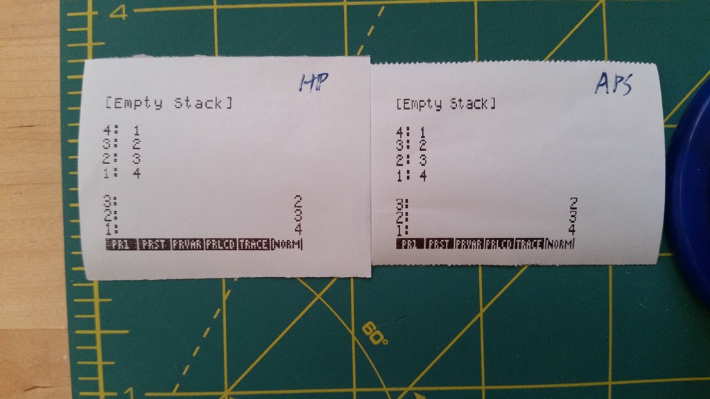
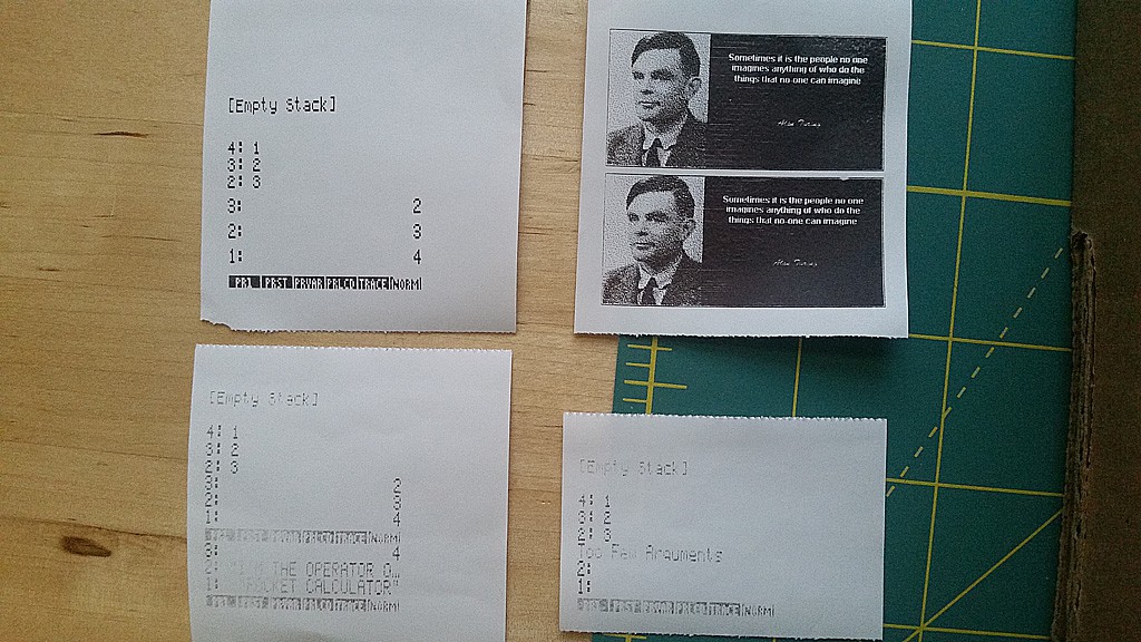
This worked best. Here is the new final result, side-by-side with a real HP printer output. I set my contraption near the HP printer, so their bathing in the same sunlight and outputting simultaneously from the same IR signal.
![]()
Pretty darn close! I marked the two printouts 'HP' from a real HP82240B printer, and 'APS' from this project using the APS EPM203-MRS driver (the GoojPrt driver is also supported. The Kashino driver is incomplete -- that printer doesn't have flow-control, so I would need to add transmission pacing before I could call that 'supported'.)
This takes it about to the limit of what I intend to do on this project at this time. The physical differences in the printer mechanisms preclude getting the output pixel-perfect, but I think for practical use, this is more than serviceable.
The next thing I want to do is shoot a video of the thing live and in operation, but I need to get a tripod and a camcorder from a friend. In advance of that, I think I'm calling this project is 'complete' for now. I do intend to come back to it for the 'monitor' implementation to support various enhancements, but I have other projects calling for my attention just now, alas.
Next:
In the near term, I'm goign to try to shoot a demo video. Also, I would like to get a better power supply for the GoojPrt so I can turn up the darkness on that unit.
Longer term, I may revisit it for the 'monitor' enhancement.
Longer longer term, I may look at interfacing directly with the printer core, rather than the printer with module. The printer core is closer to the metal of the stepper motors and the thermal head. This part is cheaper than these panel printers. The panel printer I am using here is useful for integrators, because it has a controller board that exposes a high-level print language and controls those lower level electronic elements. However, why do I need that here? This controller is already low-level, so why not interface directly. And SOOOO much more CONTROOOOOL! But that sort of project -- fascinating as it might be -- is really more towards producing an actual product you want to build and sell in scale, rather than just fiddling with stuff one-off. So, that will probably never happen. Alas...
-
Success! I'm the Operator on My Pocket Calculator
07/19/2017 at 18:04 • 0 commentsSummary:
Printing to physical printer is now working with both the GoojPrt and APS EPM203-MRS units.
I am now moving onto optimizations and enhancements.
Deets:
I implemented two physical printer rasterizers for two of the sample printer cores: the GoojPrt unit that I was originally going to use, and the APS EPM203-MRS unit that I got later. They both print correctly (with some caveats):
![]()
APS EPM203-MRS output is top two, GoojPrt output is lower two. So, printing is a-happinin'! Yay!
There are two caveats, though:
- as mentioned earlier, the electrical design of the GoojPrt leaves some things to be desired. As you can see in those two printouts, the output is rather faint. This is easily addressed with a command that specifies heating/resting times for the thermal head, but using that so far has only resulted in power supply droops that reset the printer, so I am holding off on addressing that now until I get a better power supply. I find this annoying, but the code must go on!
- also as mentioned earlier, the APS unit's firmware has the annoying tendency of advancing the paper when printing bitmaps (and everything in this printer project is treated as bitmaps so as to realize the 82240 character sets). You can see the effect in the top right printout, where there is noticeable space between the lower printed 'lines'. Those are on separate strips of output bitmap. It doesn't look incredibly horrible here, but that is just good luck. If I were to print, say, a graph, then you would see the intervening paper advances.
That printer happens to have a 'reverse linefeed' command, which in principle I could use to compensate, but the maddening thing is that the gratuitous paper advance only happens if there is a pause in the print data stream greater than some unknown amount (around a second or less). If the pause is below that threshold, there is no advance. You can see this in the top lines of that printout, where the successive rendered bitmaps (three in that case) are output in rapid succession.
This is maddening to me. I am scouring the datasheet to see if this is some feature that can be turned off. I may disassemble the printer's firmware to see if I can find a way to stop it (I disassembled the firmware of the Kashino last week for an unrelated activity).
So, now I am trying to fix the power supply issue for the Gooj, and the gratuitous paper advance issue for the APS. After resolving those, the project will technically be 'done', but is anything really ever 'done'?
As mentioned before, as an enhancement, I want to implement a command-line interface 'monitor' program that runs on the USB side. It would do things like manage settings and whatnot.
As an additional feature, I want to be able to realize some secondary functionality such as:
- send decoded IR to USB port; this would realize an HP82240 to PC adapter for receiving raw data from the calculator for... whatever!
- forward data from USB to printer port; this would realize an PC to thermal receipt printer adapter
- etc.
After that, I should be able to mark the project 'completed'. My favorite task to cross off!
Next:
I want to resolve the annoying paper advance issue in the APS printer, and the annoying power suck issue in the GoojPtr.
I need to capture a video of the printer in operation for the blog.
-
Thoroughly Removing The Uncommon Words of Anguish
07/18/2017 at 14:09 • 0 commentsSummary:
Reading datasheets can be fun!
Deets:
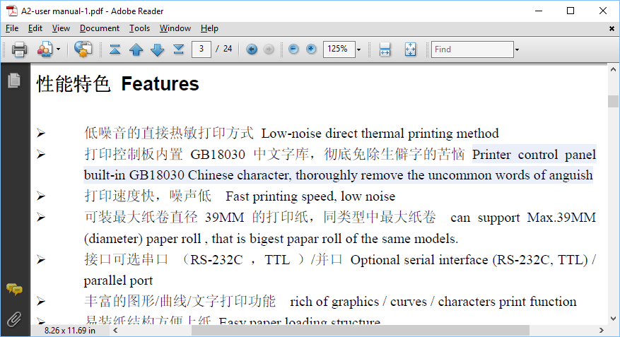
While coding up the rasterizer, I was rummaging through the datasheet for the Kashino printer. I came upon this statement in the "Features" section of the User Manual:
"Printer control panel built-in GB18030 Chinese character, thoroughly remove the uncommon words of anguish."
I can't make this up; q.v.:
![]()
(I don't know why the highlight is there -- it's that way in the PDF itself (with other things).)
I do very much appreciate having access to the the document, but I think they might have fallen short of their stated goal because I did utter some words of anguish upon reading this. But maybe my words were too common to have been thoroughly removed.
Next:
Back to work coding printer rasterizers....
-
My Three Sons; Mike, Robbie, and Chip
07/17/2017 at 23:27 • 1 commentSummary:
I was tired of waiting for my printer to come in from China, so I bought a similar one that ships statewide. Then I realized I actually had a printer on-hand all along from a project some 4 years back. No sooner than I dug up the old printer, the other two arrived the same day. Sheesh. So now I have an embarrassment of riches.
Now, I mount the printers and do intial tests with the integrated system -- finally!
Deets:
In impatience to receive my printer module, I went back to eBay and looked to see if a similar module is available from domestic shipping, which should take less time. There was, and not for not much more cost. Further, as best as I can tell, this is the more premium module on which the other module claims compatibility. This is the APS EPM203-MRS. Moreover, I could find a real datasheet on this model. Still, it would take a week or two to get it in.
Well, this morning (Friday; sorry, late post. It takes me more time to compose these posts than it does to do the work on which I'm reporting!) I awoke with the realization that I actually already have a thermal printer from a project I was doing for a client some 4+ years back. That was a 'Kashino CSN-A2-T'. I did dig that up.
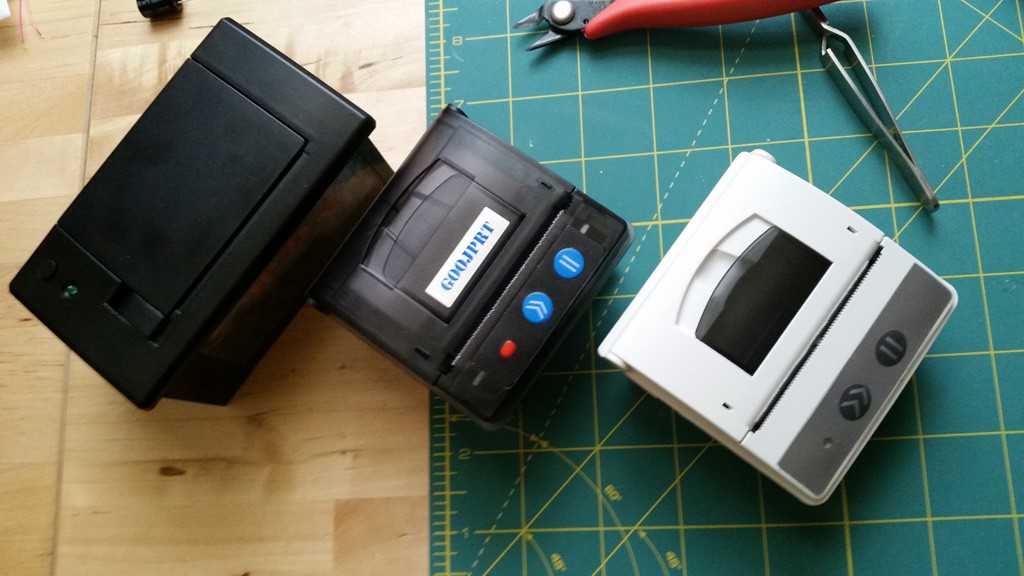
Then when the mailman came, a miracle: both my domestically ordered APS module /and/ my Chinese 'GoojPrt' module arrived! Yikes! Too many printers! Here they are:
![]()
Mike, Robbie, and Chip -- err... 'Kashino', 'GoojPrt', and 'APS EPM203-MRS'.
They all three have 'TTL' serial, which I measured to be 3.3 V logic (happily; so I don't have to add level shifters). Howver, the Kashino out-of-box only does 'hail, Mary' style serial, and by that I mean there is no flow control. I can open it up and hack it it onthe controller board (it's there), but the Kashino is now less relevant since my other modules came it.
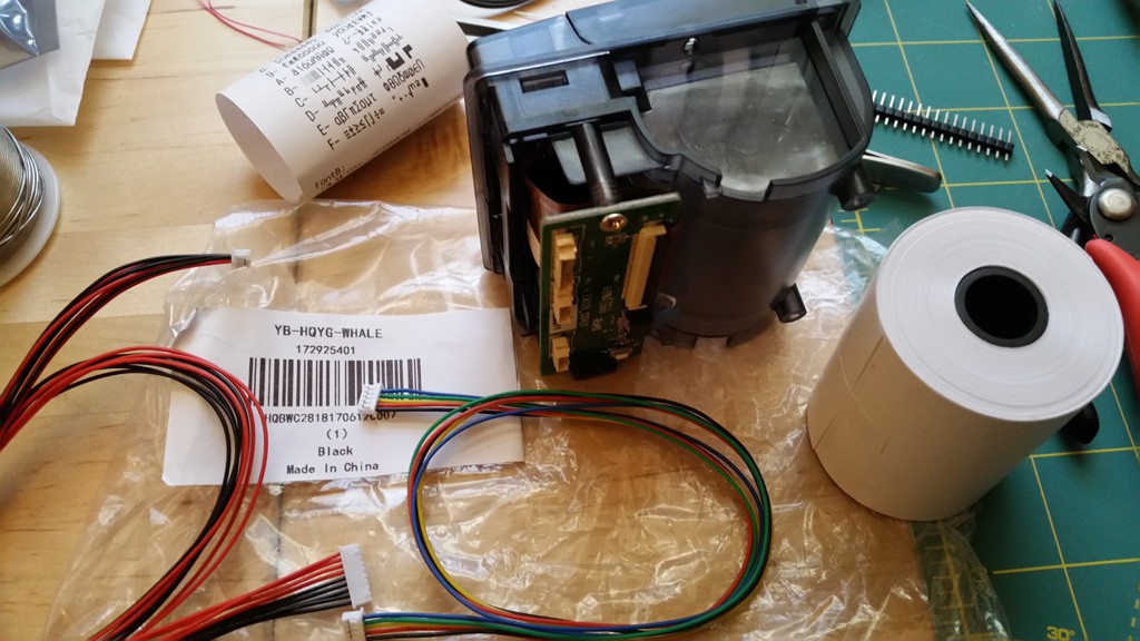
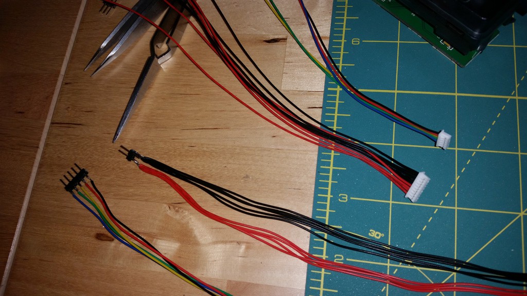
To my dismay, the APS printer module is just the module -- no connecting cables! Yikes! But there was unexpected hope, because the GoojPrt did come with cables. Here is the 'unboxing':
![]()
Fortunately the important connectors are the same on the GoojPrn and the APS, so the Gooj wires will work in both instance. And... since I need to solder the other end of the cable to the controller board, and since the wires are pretty long as it is, that means cutting each in two. So, another set of cables! Yay for wasting money on too many printer modules! I cut the cable assemblies and soldered some pin header terminations on one pair, which will be convenient for me to stick it in a breadboard and/or connecting to the FTDI adapter for testing before getting into the real code for the controller board.
![]()
Now, time for a sanity check.
I never could find documentation on the GoojPrn, but it looks suspiciously like the APS unit. I found documentation on the APS unit, and have some for the Kashino, too. The Kashino claims that you hold down the Paper Feed button while powering on, and a test print will spew out. The APS claims that you hold down the Online/Offline button while powering on, then click Paper Feed twice, and then releasing the Online/Offline. OK. None of this worked at all on any of the three printers.
The Kashino and the APS printer just could not be made to do anything interesting with those buttons sequences, and the GoojPrt would only print CP437 once and stop. WTF? Incidentally, the GoojPrt and the APS both come with a strip of paper that is the test page printout, so I know what it should look like. If one came with the Kashino, it's been lost to time. On the Kashino, it just did a paperfeed like the paperfeed button should do, and the APS simply gave me a blank stare. Ah, the joys of documentation on these things.
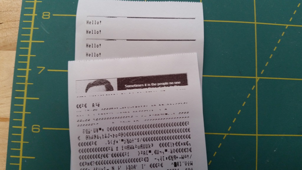
In desperation to see something interesting happen (I mean, surely all three can't be broken?) I went ahead and wired them up to my FTDI. I guessed on COM port speed -- apparently the Kashino is 19,200 and both the GoojPrn and APS are 9600 -- and sent a simple "Hello!" message. Yay! It printed! So wtf could be the problem?
Moving on again, I tried concoting a binary file of an image. I first had to process a monochrome bitmap and then hex-edit it with the printer commands. It should print by dumping the data to the printer.
This totally did not work; all I got was random junk from the GoojPrt. On the other hand, I don't really have a datasheet for the Gooj, only the APS and Kashino, so maybe the language is different. It definitely is different between those two printers for things like graphics. (Text mode is a no-brainer). Since the APS and Gooj have the same connector, and also because the APS has hardware flow control, I decided to hook up the APS, and concoct the image in it's native language for which I have real docs.
The results were not exciting:
![]()
Ugh. What NOW! I do get a little printout of the graphics, then it croaks and all Hell breaks loose. I decided to pull back and make a file with just a few graphics lines, and that worked OK, and I could still emit "Hello!" just fine in between and then send more graphics just fine. Hrmrmrmrmm!
I went to Google and searched and searched and at best I could find some reference to folks having somewhat similar troubles and flashing firmware. In desparation I did something a little dumb: I flashed the GoojPrt with firmware intended for the Kashino. I don't really know what I was thinking, but it does work -- sort of. The buttons no longer function, but all the printer is OK. I can't generate a test page from the buttons anymore, but I can do the same by issuing the command over the serial port.
It wasn't entirely stupid for my to flash the Kashino firmware -- I guessed that the units were very similar because I could issue the same commands (that I could make work) on both those units. It was an act of desparation for me to flash in this manner, but it is still working enough. But it did not really solve my problem, so I do regret it. Plus, I can no longer feed paper from the front panel buttons. :(
I fiddled with this for hours, and eventually went to bed, defeated and dejected.
Then I awoke the next day with a kooky idea: let's look at the power bus. I mean, I'm using a regulated 7.2V 1A power supply, SURELY that is enough, right?
Well, I hooked it to the scope and the V+ line did take a dip when printing my message. But still not a shocking amount. So I tried it with the 'Test Page' on the GoojPrt unit, since that's the only one that did anything when I used the magic button sequence.
Well, that caused a much bigger dip. It then occurred to me that maybe what was happening is that the dip was going below the point that the on-board regulator could accept and still maintain it's 3.3V output, and that the processor might be resetting. It was a little difficult for me to notice at first, because the printer has the annoying habit of flashing the online LED when it is online, so the flicker of the LED due to board reset was not really visible versus the flicker of the LED in normal operational mode.
I tried printing out a longer text message: "Hello, I love you. Won't you tell me your name?" and the printer did reset on that message. So, more black dots == more heat == more current == more power demand, and too much for my 7.5V 1A (!) supply to deliver. (Or it has a different taste in musik.) So I pulled out a 5V 3A supply (I didn't have a 7.5V one, but 5V is within operating specs). SURELY that would be enough, right?
That worked... better! I did get most of the test page printout until it got to "FontB" and then it failed. The FontB printout section has a denser print, so probably the power suck again. Coincidentally, I noticed something: Oh, Jesus, the wire carrying power was quite warm! OK, stupid me, I used too low a guage power line (I was using one of those breadboard jumper wires with the Dupont ends), and was measuring on the hot side of it, so even the dips I saw were doubtlessly smaller than on the other side of that wire. Stupid monkey, stupid!
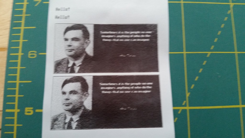
I substituted a bigger piece of wire and then: Bingo! I got the image!
![]()
(sorry, blurry; need a tripod) Sweet mystery of print, at last, I've found you!
OK, I feel a little silly for the power thing; but, Sweet Jesus! this thermal does suck the power down!
However, you may notice the space between the two images. I did not put that there. The APS unit put that there. This might be aesthetically pleasing in some practical receipt printing cases, but I do not want that space at all, since I am rasterizing all my output, and need it to stack up without gaps. I did notice an oddity: If I send the images in rapid succession, then they ARE contiguously, but if a pause a bit, the printer adds the gap. Ugh; I don't have time for this.
In desparation, I formulated a Kashino image and connect the GoojPrt, and that did not exhibit the gap. Yay! For that. But, the image was quite faint. Boo! For that. There is a command to increase the heating time, making the print darker, but then that returned me to the rebooting problem, even with the thick wires. I even added a 1000 uF cap in hopes of supplying transient demand, but to no avail. Sigh. I decided to move on and deal with the faint output for now so that I could finish code, and I'll come back to upgrading the power supply later (I'll have to get one; I don't have a 7.5V 3A). Anyway, all this is wired through the breadboard now so that I can swap connections easily, so all the more reason to move on for now.
I suspect that the APS unit has a better electrical design than the GoojPrt, but that I can still use the Gooj if I can get a beefier supply.
Now, enough of hand-crafted graphics commands -- time to code some rasterization!
Next:
Having gotten past printer quirks, it's time to implement the rasterizer fer real. I think this (at least!) should be straight-forward, especially since my previous work involved me manually cooking up printer commands to realize a successful graphics print-out. The biggest additional work is the integration into the rest of the system, and I think I have that implemented and tested enough such that that will not be too onerous.
-
♫ I've Got (too much) Power! (gonna make you sweat) ♫
07/13/2017 at 18:07 • 0 commentsSummary:
The BluePill board is powered directly from the 5V USB line. The printer requires more power than USB can supply, necessitating an external supply (e.g. 5V wall adapter). Wiring the 5V from an external supply then precludes the use of USB, because the circuitry would directly connect that to the computer's power bus.
Some minor surgery was done to avoid damaging the PC when the USB is connected. This was done two ways: good, and better.
Deets:
The printer requires more power that the USB can supply, so an external supply of some sort is needed. It could be batteries, but in my case I am going to use a 5V regulated 'wall wart'. This presents some challenges, though. The design of the BluePill has the +5V USB line connected directly to the input of the 3.3V LDO regulator. Some things that can be done:
- if only the ground of the BluePill is connected to the ground of the printer, this would be OK, except then the BluePill will always have to be connected to some USB source of power. Silly.
- if the power supply for the printer is connected to the BluePill, this would be OK, but then it would be dangerous to connect the BluePill to the USB port of a host, because that would couple the printer power supply into the host's USB. And you know someone will do that because the jack is there, and anyway I do want to do it because I want the USB CDC functionality. Undesireable.
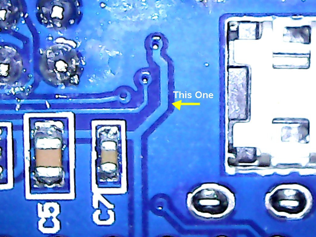
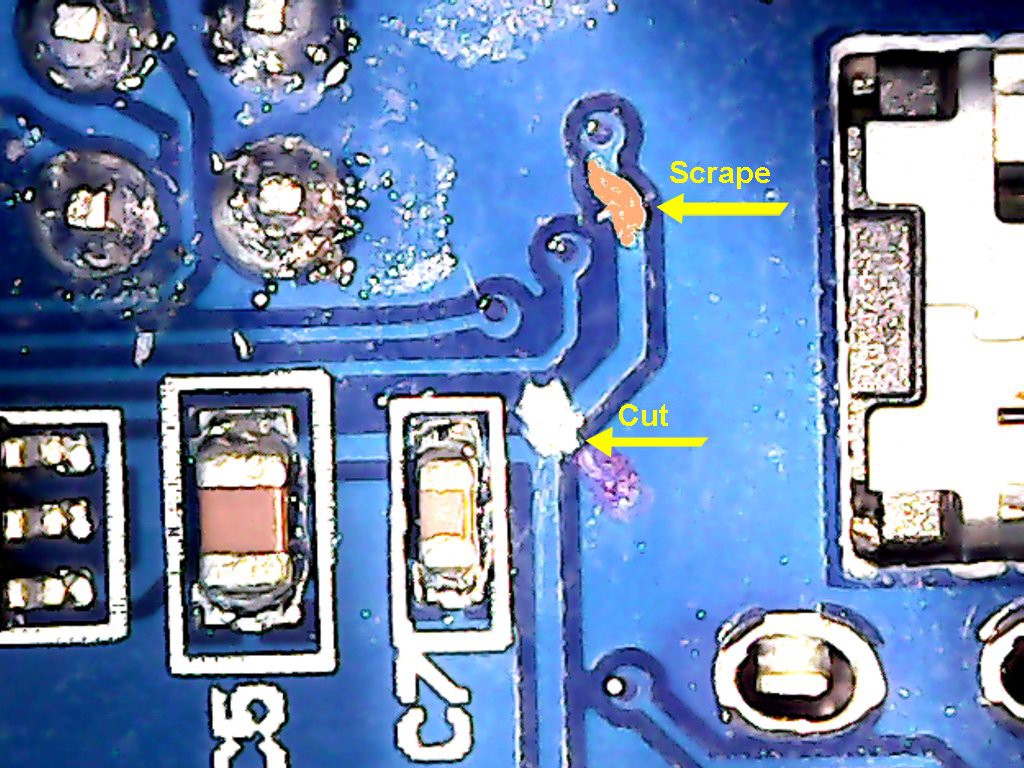
So, much as I am loathe to do it, I need to do some PCB surgery. The first surgery is to disconnect the +5V USB line from the input of the regulator. Here is where it is located on the back of the board:
![]()
So, that trace must be cut. Here it is cut:
![]()
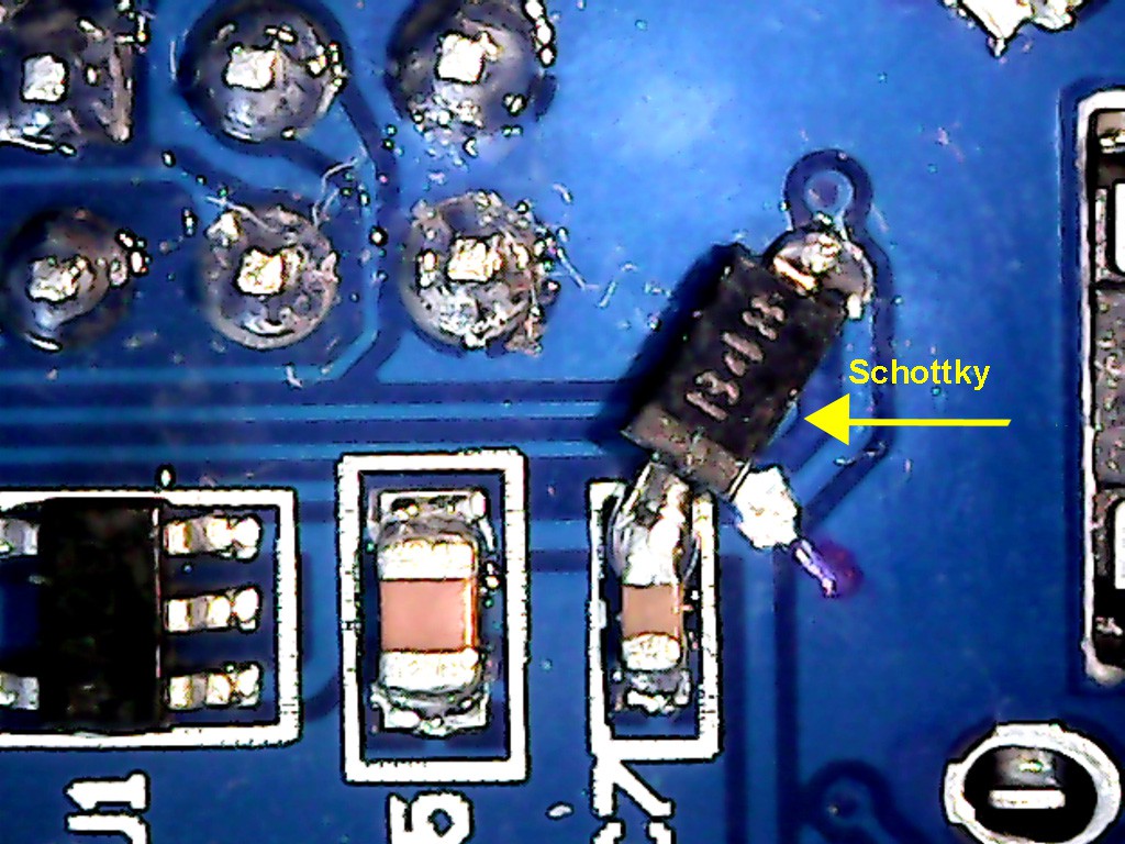
Now I can power the board from the external 5V supply, along with the printer module. But, it also means that I will always need the external supply to do the USB. I can fix that by adding a Schottky diode where the trace used to be. That way, USB can power the CPU board if there is no external supply, and the external supply will be blocked from powering into the host if it is there.
Coincidentally, I have some MBR0540T1 Schottkys, which are just about the correct size. I scraped off some of the solder mask near the via (you can see the scraped area in the picture, above), and soldered the diode from that spot to the other side of the cut trace (borrowing the pad from C7 for the diode's cathode).
![]()
As you know, we typically use Schottkys because they have a low forward voltage drop of about 0.2 V, but really, since the 5V is going into a 3.3 V regulator, you could use a typical silicon diode (0.7 V) just as well.
Now I can use the USB with safety and confidence! Well, almost. If I want it to be really robust, I also need to add another Schottky on the external supply side, so that the USB doesn't try to power the printer if the external supply is not present. This is because the printer takes too much power for the USB to supply, so mI ight as well prevent that accident from happening, too. This won't require board surgery, but rather a through-hold Schottky can be mounted on the 5V pin of the board. (I haven't done this yet, so no picture, but this one is trivial since the 5V pin is clearly marked on the board. Just be sure the diode is pointed the correct way -- with the banded side towards the board, away from the power supply.)
In retrospect, I'm a little surprised that the manufacturer didn't splurge on adding the diodes. They did splurge on adding two crystals, and frankly I'd rather if they simply put the one 32.768 KHz crystal, leaving the 8 MHz unpopulated, and redirected that cost into these protection diodes. The chip has a PLL that can synthesize the high frequency clock and phase lock it onto the low frequency crystal, so you wouldn't lose any capability by dropping the high frequency crystal. But, hey, I didn't design the board, and I'll definitely still take it considering the absurdly low cost.
OK, back to printer interfacing....
Next:
More printer interface code.
-
♫ Flash! (aa-aahh!) Saver of the Usersettings! ♫
07/12/2017 at 19:02 • 0 commentsSummary:
It occurred to me that it would be useful to save some configuration in a non-volatile manner. This board and this chip does not have any conventional non-volatile storage (e.g. EE or external serial EE), but there's plenty of pages of unused program memory, so I use the last one to be used for infrequently changed NVRAM settings.
Also, I validated my HP82240B rendering engine.
Deets:
Over the past couple weeks it occurred to me that this interface board has some utility beyond the primary intent of being an adapter to a receipt printer to emulate a HP82240B -- for instance, it could be also useful as an IR-to-serial adapter, forwarding IR data to the USB port (or UART if you need to, and don't have a printer there). This is easy enough to do and it's easy enough to set the system up in that manner, but this state will not persist boot-to-boot. So, time for some persistent settings.
Most non-volatile memory is known for the exhaustion phenomenon, so you generally try to avoid burning/erasing except when needed. Frankly, for this application: storing user settings, the burning/erasing will naturally happen very infrequently since it is a user-initiated activity that is only occaisionally performed. I'm sure all readers of this log post will have long since passed on to the hackerspace in the sky before they have exhausted the million flash erase-write cycles for settings changes. That being said, like my friend Ming the Merciless says: "I like to play with things awhile, before annihilation." So I'm going to go a little further with this featurette.
The flash is organized in 'pages' which is the smallest unit of erasure. On this part, the page size is 1 KiB. That should be more than enough for my setting storage -- at least until I have a need for large object like strings -- but for now it's just a few integers.
What I'm doing in this implementation is to store a struct of my settings in the last page of flash on the device (leaving all the previous pages for the program). That last page will have zero or more copies of the settings. The last copy of the settings is considered the current values.
So, upon boot up, the code searches for the last copy of settings, and initializes the RAM-based copy with that data. If it doesn't find any settings, then it will intialize the RAM-based copy with the baked-in default values. The rest of the system then proceeds to use whatever is in the RAM-based copy.
I want to have the RAM-based copy because I want to be able to change settings on the fly via the monitor interface (yet-to-be-implemented; it will be on the USB CDC). When you have the device dialed in the way you like, then you can persist the settings.
Persisting works like this:
- find the last valid settings image
- see if there is space after it for one more settings
a) if there is, that is where we will be programming
b) if there is not, erase the page, and let the start be the place we will be programming - program the flash at the place we located
A simple scheme, but I wanted to document it here. This way, the flash exhaustion is reduced by a factor of how ever many settings structures can be fit on a page, which presently for me is 64 (but this will go down as I add more settings, but still).
Other News
I did validate my HP82240 printer rasterizer functionality. It was a bit painful, but I managed to dump the image over the serial port, then meticulously hand-craft a bitmap of the data. For example:
0E 00 00 02 00 00 02 00 04 0E 00 00 00 00 00 00 00 00 00 00 00
C2 07 00 02 00 38 02 00 04 08 00 00 00 00 00 00 00 00 00 00 00
42 B0 3C 47 04 04 87 E3 25 08 00 00 00 00 00 00 00 00 00 00 00
C2 53 45 42 04 38 02 14 14 08 00 00 00 00 00 00 00 00 00 00 00
42 50 45 42 04 40 82 17 0C 08 00 00 00 00 00 00 00 00 00 00 00
42 50 3D 8A 07 44 4A 14 14 08 00 00 00 00 00 00 00 00 00 00 00
CE 17 05 04 04 38 84 E7 25 0E 00 00 00 00 00 00 00 00 00 00 00
00 00 04 80 03 00 00 00 00 00 00 00 00 00 00 00 00 00 00 00 00
renders into:
v       v       v       v       v       v       v       v       v       v       v
.###.....................#.......................#................#......###....
.#....#####..............#.................###...#................#........#....
.#....#.....##.#..####..###...#...#.......#.....###....###...####.#..#.....#....
.#....####..#.#.#.#...#..#....#...#........###...#........#.#.....#.#......#....
.#....#.....#.#.#.#...#..#....#...#...........#..#.....####.#.....##.......#....
.#....#.....#.#.#.####...#.#...####.......#...#..#.#..#...#.#.....#.#......#....
.###..#####.#...#.#.......#.......#........###....#....####..####.#..#...###....
..................#............###..............................................
Tada!
That bitmap was captured from within the physical printer rendering task, so that means data is now flowing correctly from sender (HP28C calculator in my testing), to IR detector, to IR decoder, to HP82240 rendering engine, to physical printer rendering engine. So it's getting close to being a working system, once my printer arrives (and I have coded and debugged that module).
Next:
Now I have to transform that bitmap into graphics commands for the physical printer.
And then there will be cake.
-
Fontastic!
07/11/2017 at 17:32 • 0 commentsSummary:
My hunting for an existing HP82240B font paid off, and a couple days drugery was avoided. I have converted the found glyph images into my personal format and have implemented the rendering engine for the HP82240B data stream.
Now I am off to work on the physical printer driver. Or not.
Deets:
As mentioned in a previous post, I wanted to look for some existing TTF fonts that might already exist for the HP82240B printer. Sometimes folks create these for simulators to give an authentic look to the output. Having such would save me many hours of manually digitizing the 448 code points (well, OK, about 1/3 less than that of /distinct/ code points) from printouts since I already have a tool for rasterizing TTF to my personal font format.
At first I found 'HP Printer' somewhere, but it was not for this printer, so no good. In the end, I never found a TTF font, but I did stumble across a printer simulator produced by Christoph Gießelink
http://hp.giesselink.com/hp82240b.htm
and somewhere in my travels (I can't recall where, now, alas; so much searching) I found source code bearing this imprint:
/*
These are the HP82240B font tables for the Roman8 and ECMA94 character set.

The code is part of my HP82240B Printer Simulator available at
http://hp.giesselink.com/hp82240b.htm.

This code is distributed in the hope that it will be useful, but WITHOUT ANY
WARRANTY; without even the implied warranty of MERCHANTABILITY or FITNESS FOR
A PARTICULAR PURPOSE.

There's no licence behind, so use it in any way you like it.

May 2012, Christoph Giesselink
*/
which I interpret as being functionally public domain.
The data was not useable as-is because it is in column-major form, and I need row-major. So, 'big whoop', I wrote a little one-off program (significantly derived from my existing TTF rasterizer -- it wasn't that much new work) to do the relevant rotations and emit font data.
I have no way of verifying it at this time, but the rasterizer program emits comments showing the image form of the bit pattern, so it seems to be good. Here's a couple examples:
a couple from the ASCII section
	//glyph for 0x37 (7), 8x6, at offset 184
	0x00, 	//........
	0x1f, 	//#####...
	0x10, 	//....#...
	0x08, 	//...#....
	0x04, 	//..#.....
	0x02, 	//.#......
	0x02, 	//.#......
	0x00, 	//........

	//glyph for 0x33 (3), 8x6, at offset 152
	0x00, 	//........
	0x0e, 	//.###....
	0x11, 	//#...#...
	0x0c, 	//..##....
	0x10, 	//....#...
	0x11, 	//#...#...
	0x0e, 	//.###....
	0x00, 	//........
and one from the high set:
	//glyph for 0x9f, 8x6, at offset 1016
	0x00, 	//........
	0x0e, 	//.###....
	0x12, 	//.#..#...
	0x12, 	//.#..#...
	0x12, 	//.#..#...
	0x00, 	//........
	0x00, 	//........
	0x00, 	//........
and so on, for the 'Roman 8' and 'ECMA94' sets. Yay! Time saved. (I did send a 'thank you' note to Christoph Gießelink for his work.) With that leg-up, I proceeded to implement the printer state machine, and rasterizer.
As mentioned, for the rasterizer I am reusing some character blitting code I had already produced for another project, so that part was pretty easy. I did hack it to support wide characters and underline mode, and exploit some peculiarities of this printer.
The state machine wound up being pretty easy, too. There's just a few states for TEXT, GRAPHICS, and ESCAPE states. The TEXT state checks for a couple special characters, and otherwise does a character blit of the incoming character. The GRAPHICS state instead sends the data to a 'bar blt' routine, which sets the pixels in a vertical bar according to the bit pattern of the received data. The ESCAPE state checks for the few known escapes and otherwise interprets the data as the 'length' parameter before transitioning to the GRAPHICS state.
The machine invokes some callbacks that the user is expected to implement. Notably, the 'image complete' callback is invoked when a carriage return is encountered. The expected implementation would be to do something useful with the completed bitmap before returning (whereupon it will be cleared and ready to be re-rendered).
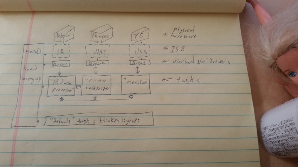
It might be handy to have a block diagram of the system at this point:
![]()
(sorry, I don't do Visio; takes too long) Short story:
- main() cranks up the hardware and subsystems. There is a tool-generated 'default' task that I don't really need, but I choose not to fight the tool, so I keep it around to do debug things, like monitor the heap and turn off leds I use in debugging.
- the physical hardware devices are directly managed by ISR code, which indirectly interacts with the rest of the system through queues and event notifications. This makes the hardware devices principally look like byte streams.
- the bulk of the system produces/consumes events and data to/from those streams, and is (currently) realized with three 'tasks' (threads/processes):
a) IR data processor
consumes incoming IR data and runs the HP printer rasterizer machine. Since that machine invokes it's event callbacks, those callbacks are therefor running in the context of this task.
b) Printer rasterizer
is notified of completed bitmaps from the IR data processor, and transforms those into native printer commands for the physical printer.
c) Monitor
I haven't done any work here, but this task is responsible for running a command interpreter attached to the USB CDC device I recently completed. It is intended to take configuration commands and provide diagnostic debug output, and also to potentially serve as a 'tee' of the incoming IR data, so that the interface board also can serve as an 'HP IR Redeye to Serial' converter.
d) default
As mentioned, the STM32CubeMX tool generates a 'default' task, so I am just leaving it in-place for now, rather than fighting with the tool when I regenerate code. All it's doing now is sleeping, and periodically waking to sample heap usage and turn off any LEDs that may have otherwise been turned on when errors (like parity errors on IR, etc) occur. I might do something more creative with it later, or maybe I'll merge the Monitor task into this one. But right now they are separate.
The only other thing of note I think is that I'm using FreeRTOS 'task notifications' where possible, and I'm using a binary semaphore between the 'IR data processor' and the 'Printer rasterizer' because I think I must. Their interaction is pretty simply, but here it is:
'IR data processor' renders a bitmap via the rasterizing engine. That engine makes a callback that the bitmap is complete. The callback must do it's business before returning, because upon return the bitmap will be cleared and reused for further incoming data. I could do all the subsequent printer data rendering right now, but I chose instead to do that in a separate concurrent task.
The original printer was designed as a one-way communications system, and in that design the sender must be conscientious about pacing it's output such that the physical printer has adequate time to do things like move it's print head, etc, because there's no communications channel back to signal that those things are completed. So it's a 'Hail Mary' system. As such, I have plenty of time between lines being sent to re-rasterize and send to the new physical printer (plus, the new printer is much faster and quieter).
That being said, I prefer to be more robust, and I've got the flash and ram to do better, so I'm instead implemented a double-buffer scheme where the Printer rasterizer is in a separate task, and has it's own copy of the source image. Now, when the IR data processor/rasterizer calls back to indicate that a completed bitmap has been rendered, the following happens:
- IR data processor acquires a lock (implemented as a FreeRTOS binary semaphore).
- memcpy() the rendered buffer to the secondary buffer
- release the lock
- task-notifies the Printer data processor that there is a new bitmap to process
- goes back to immediately being ready to process more IR data
and then the Printer data process will awaken... - Printer data process awakens from the task notification
- acquires the lock on the secondary buffer
- parties on the data however it wants
- release the lock on the secondary buffer
- goes back to sleep waiting on a new task notification
I think this decouples the two subsystems (except of course for the semaphore and task notification) and allows them to process at their leisure. Stalls will eventually be propagated back through the various locks, with critical failure occurring when the IR data queue overflows and otherwise naturally draining back out whenever the stall condition is removed.
This arrangement turned out to be handy sooner-than-later when I implemented the 'Reset' command in the HP data rasterizer. That command is implemented as sending 12-lines of simulated printer data to be rasterized. I didn't need to put in any artificial delays -- I could send it full throttle. I'm looking forward to having the physical printer to see how that command executes....
Next:
I haven't really been able to test all of this to my satisfaction because I am only rendering to in-memory images, and passing them off to a second task to be processed. Now I can either:
- work on the monitor task, so I can, say, hex dump the output to study offline
- punt on testing this for now, and work on implementing the Printer data rasterizer
I haven't decided which, they both have their charms...
HP 82240B IR Receiver and Printer Interface
This is an IR receiver and interface for adapting a commodity receipt printer to be 82240B-compatible.