 ziggurat29
No, it's not. A few weeks ago a gentleman asked about procuring a completed printer interface. It's been some 7 years since I did this project, so I had to refresh my memory.
I recall being concerned about using the TSOP4133 in this application. It has worked fine for me with my calculators, but I am pushing it to the limits of the specification, so notionally it could be problematic with a different calculator or different batches of TSOP's. I had dealt with the fringe cases in software, but I was still wanting a more confidently robust alternative. I planned to implement a new demodulator based on an IrDA module, which should definitely work with the signaling. The code will be different, since modulated data will be received (the TSOP demodulates with envelope detection, but we'll receive the individual bursts here). The 32 kHz carrier can easily be handled as as a direct interrupt source since the BluePill is running at 72 MHz.
Along the way, I discovered that a feature I thought I had implemented was not: the ability to use the interface board standalone (i.e. no printer) as an HP-IR-to-USB adapter. The gist being that instead of directing the IR to the printer rasterizer, instead send it to the USB-CDC serial port. So I needed to code that.
I had started this back in 2018, but I apparently damaged my IrDA module -- possibly spending too long soldering to the tiny device. I had recently picked up some other IrDA modules that were surplus from Electronic Goldmine -- the Sharp GP2W0004-YP. So tiny!
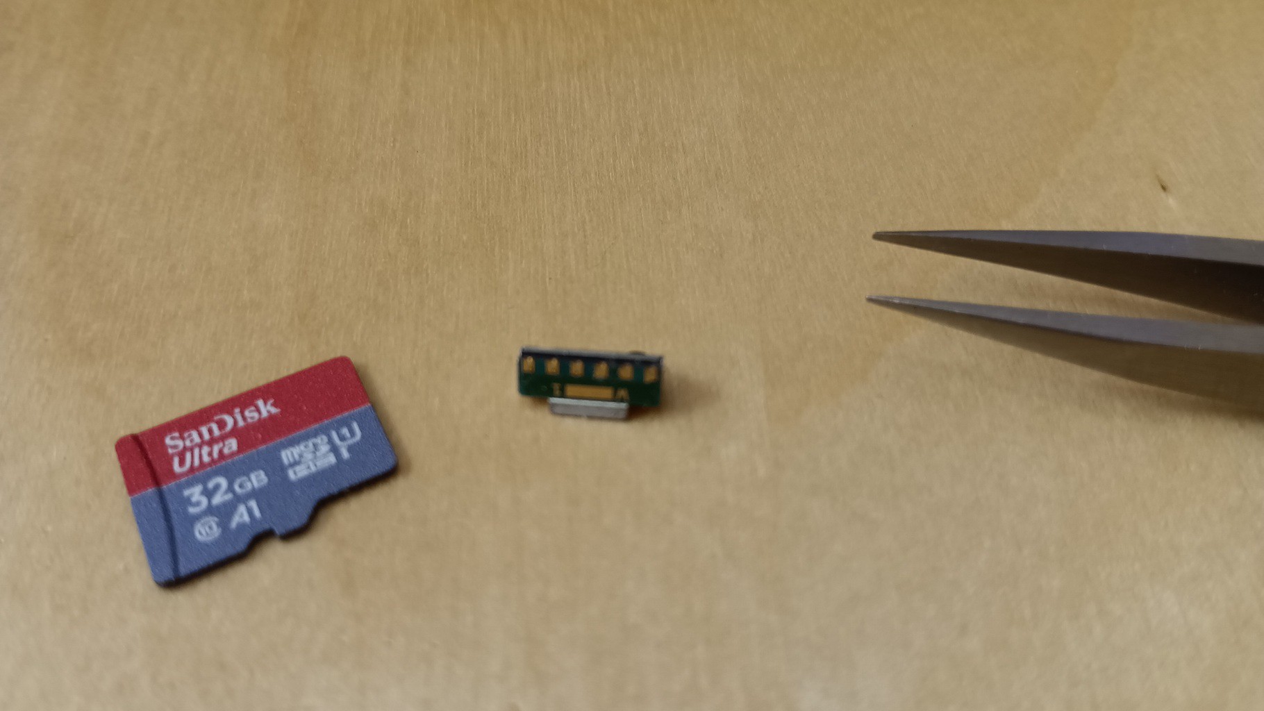
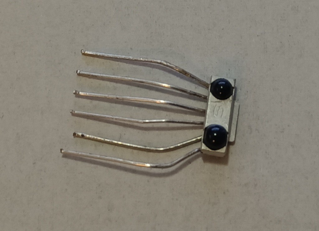
However an idea struck me to solder on some rigid wire (lead clippings from resistors) in a dispersive fan pattern, and subsequently bend them parallel to a 0.1" pitch. Then the SMD device becomes breadboard-friendly.
I'm not using these for actual IrDA here, but I decided to hook them to pins that could be configured to a serial port so that I can fiddle with IrDA later (for a different project). Here those lines will be configured as an external interrupt source for the RX signal, and a PWM for the TX signal though it is not relevant in this case. Or is it? I mean, I've now got an emitter for free, maybe I should also support sending HP IR signals? It's not meaningful for the original printer use-case, but might be interesting in the alternative adapter use-case.
That particular pin when not for UART can work off timer 2 channel 3 in PWM mode. So I can configure the TIM2 for 32768 Hz, 50% PWM, and gate the signal. I was previously using TIM2 as the system tick, so I moved that to TIM3. I use TIM1 as the bit clock. Actually, it's 1/4 bit clock, because the bursts are 1/4 a bit period.
The signaling scheme is a kind of 'biphase-level' signal where each bit has a burst in either the first or second half of the bit time (the burst lasts a quarter of the bit time). If the burst is in the first half, it is a '1', and if it is in the second, it is a '0'. There are 12 bits transferred (4 parity and 8 data) and 6 half-bits for framing (three for sync and three for stop). So a total of 15 full bit times.
In the interest of simplicity, I encode these 15 bits as 30 half-bits representing the burst/no-burst state for each half bit period. In this way, the machine (operating at 4x the bit timing) clocks out the encoded bits in two phases: phase0 conditionally turns on the signal to start a burst if the encoded bit is '1', and phase1 unconditionally turns off the signal. This this encoded-bit-clock is a multiple of the carrier frequency, it is possible to make a picture-perfect output waveform. This fits in a 32-bit word and has two spare bits which I use as a sentinel for end-of-frame.
Short story: encode a byte by setting sync bits, computing parity, and appending data and stop bits. Then set to phase0 and start the (quarter) bit clock. In phase0, test the high bit and start a burst if it's '1', then transition to phase1. In phase1 turn off the burst and shift the bit stream up. If it's the terminating sentinel, turn off the bit clock and we're done, otherwise set to phase1. Straightforward.
Demodulation was more involved. The existing decoder works with envelope-detected signal from the TSOP and decodes that based on the timing of transitions. In this case I will have the raw signal -- not the envelope. So my first idea was to layer on an envelope detector on top of the existing decoder. I did that seven years ago before I stopped working on it because I damaged my module. The work was ostensibly complete but not debugged. I had a bit of difficulty following my own code despite the comments, and anyway I had long since forgotten how the protocol works. So I started writing it afresh from first principles.
Discussions
Become a Hackaday.io Member
Create an account to leave a comment. Already have an account? Log In.