Summary:
The BluePill board is powered directly from the 5V USB line. The printer requires more power than USB can supply, necessitating an external supply (e.g. 5V wall adapter). Wiring the 5V from an external supply then precludes the use of USB, because the circuitry would directly connect that to the computer's power bus.
Some minor surgery was done to avoid damaging the PC when the USB is connected. This was done two ways: good, and better.
Deets:
The printer requires more power that the USB can supply, so an external supply of some sort is needed. It could be batteries, but in my case I am going to use a 5V regulated 'wall wart'. This presents some challenges, though. The design of the BluePill has the +5V USB line connected directly to the input of the 3.3V LDO regulator. Some things that can be done:
- if only the ground of the BluePill is connected to the ground of the printer, this would be OK, except then the BluePill will always have to be connected to some USB source of power. Silly.
- if the power supply for the printer is connected to the BluePill, this would be OK, but then it would be dangerous to connect the BluePill to the USB port of a host, because that would couple the printer power supply into the host's USB. And you know someone will do that because the jack is there, and anyway I do want to do it because I want the USB CDC functionality. Undesireable.
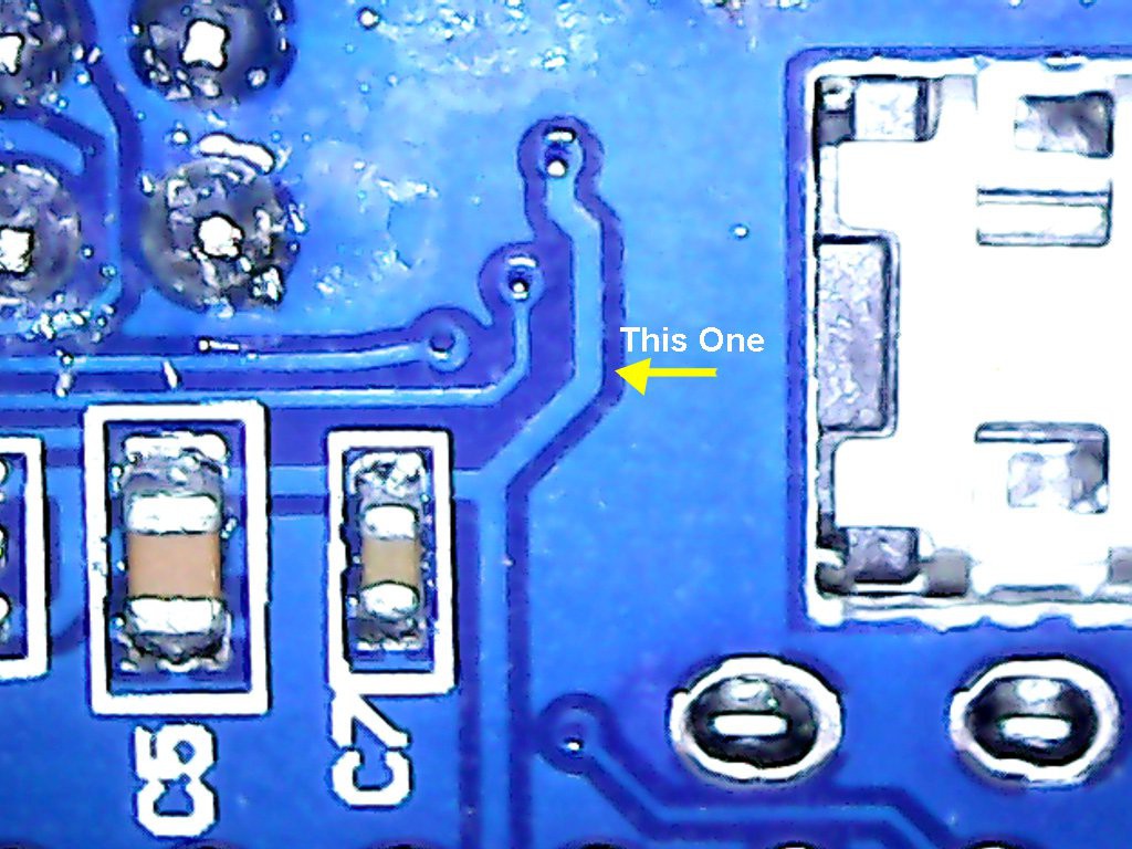
So, much as I am loathe to do it, I need to do some PCB surgery. The first surgery is to disconnect the +5V USB line from the input of the regulator. Here is where it is located on the back of the board:

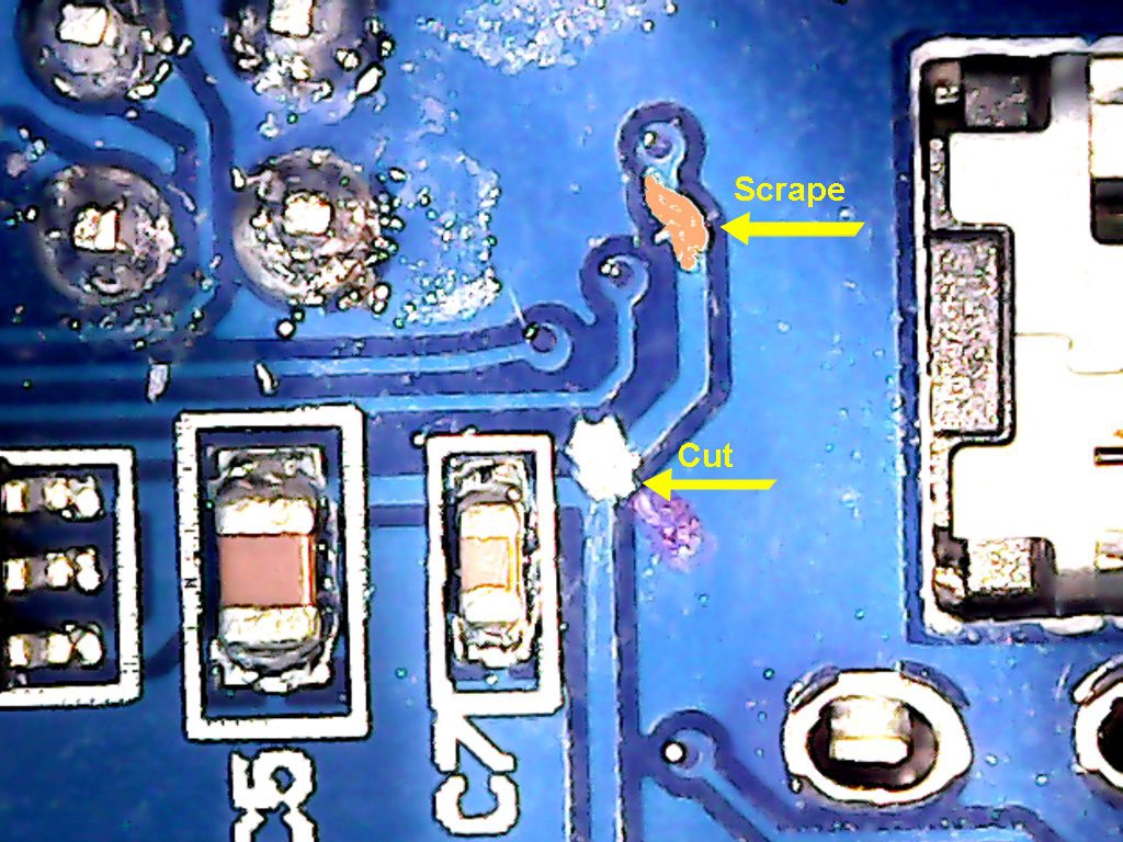
So, that trace must be cut. Here it is cut:

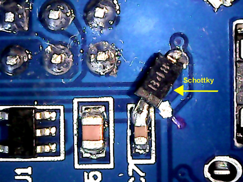
Now I can power the board from the external 5V supply, along with the printer module. But, it also means that I will always need the external supply to do the USB. I can fix that by adding a Schottky diode where the trace used to be. That way, USB can power the CPU board if there is no external supply, and the external supply will be blocked from powering into the host if it is there.
Coincidentally, I have some MBR0540T1 Schottkys, which are just about the correct size. I scraped off some of the solder mask near the via (you can see the scraped area in the picture, above), and soldered the diode from that spot to the other side of the cut trace (borrowing the pad from C7 for the diode's cathode).

As you know, we typically use Schottkys because they have a low forward voltage drop of about 0.2 V, but really, since the 5V is going into a 3.3 V regulator, you could use a typical silicon diode (0.7 V) just as well.
Now I can use the USB with safety and confidence! Well, almost. If I want it to be really robust, I also need to add another Schottky on the external supply side, so that the USB doesn't try to power the printer if the external supply is not present. This is because the printer takes too much power for the USB to supply, so mI ight as well prevent that accident from happening, too. This won't require board surgery, but rather a through-hold Schottky can be mounted on the 5V pin of the board. (I haven't done this yet, so no picture, but this one is trivial since the 5V pin is clearly marked on the board. Just be sure the diode is pointed the correct way -- with the banded side towards the board, away from the power supply.)
In retrospect, I'm a little surprised that the manufacturer didn't splurge on adding the diodes. They did splurge on adding two crystals, and frankly I'd rather if they simply put the one 32.768 KHz crystal, leaving the 8 MHz unpopulated, and redirected that cost into these protection diodes. The chip has a PLL that can synthesize the high frequency clock and phase lock it onto the low frequency crystal, so you wouldn't lose any capability by dropping the high frequency crystal. But, hey, I didn't design the board, and I'll definitely still take it considering the absurdly low cost.
OK, back to printer interfacing....
Next:
More printer interface code.
 ziggurat29
Discussions
Become a Hackaday.io Member
Create an account to leave a comment. Already have an account? Log In.