Summary:
Happy news: my IR receiver modules (Vishay TSOP-4133) arrived today!
Sad news: they do not work perfectly
Hopeful news: I am pretty sure I can still make them work correctly and reliably
Deets:
My receiver modules arrived today. As mentioned before, the HP 'redeye' IR protocol is rather different in timing from the various conventions that IR remotes use, and I had a little challenge selecting a part whose characteristics have a hope of being usable in this application. I found one that was pretty close -- but not perfectly so -- and so I was eager to look at the output signals to make a pass/fail determination for the part.
For this test, I set up the module next to a trivial hand-rolled detector. My trivial crappy detector just consisted of an old (1970's!) FPT-100 phototransistor darlington-connected to a 2N3904 and some resistors. This detector is just so I can see the raw modulated signal next to the TSOP demodulated output, and does not have any of the goodies you would want on a detector for real use so I won't discuss that further.
Here is the obligatory bench shot:
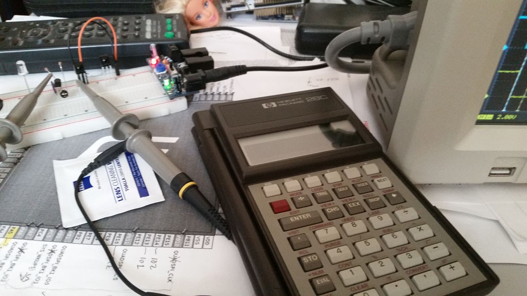
I won't relate the details of the line encoding here, since they are well documented elsewhere. But if you don't want to search, and if these few words suffice, then consider it 'Bi-Phase-L' with the further modification that a marking half-bit time is actually conveyed as a burst for a quarter-bit time, followed by a space of a quarter bit time. Otherwise, it's the same. Here's a little graphical glossary of line codes:
And here is the first trace captured:
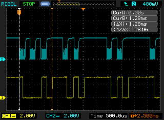
The CH 1 (yellow) trace is the TSOP demodulator, and the CH 2 (blue/cyan) trace is the raw IR signal from my crappy detector (the fuzz on the signal is the carrier, I had a lot of ambient light or you would see the carrier better, but I didn't care about that for this test).
The stuff between the cursors is 3-half-bit-times, all marking (oh, these signals are inverted, btw, so 'low' is 'marking'). As mentioned, this protocol is modified from conventional biphase-level in that a marking-half-bit-time is represented by a burst of a quarter-bit-time following by silence for the remaining quarter-bit time (a spacing half-bit is simply silence in both quarter-bit periods). I am guessing that this was done so that every burst will have a transition regardless of if you have two consecutive marks or not, but I really prefer my Manchester code the way the Mancunians intended -- it's already self-clocking, anyway. But, hey, not my spec...
OK, right away there is a problem. You can see that the first few bursts have been 'merged' into one output pulse. This is a bit of a disaster. I cried a little. But once I hardened my heart, and swallowed my tears, I noticed that the rest of the signal demodulated pretty much perfectly. You can see the whole byte when you zoom back:
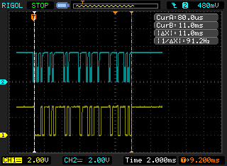
So, what does it all mean? Well, my guess is that the unit's AGC was settling during the first part of the signal reception. Most IR protocols have a fairly juicy initial burst (or use long bursts in general), and this one doesn't; it instead goes into the regular timing but just with the illegal 3-half-bits-marking sequence. I further suspect that the rest of the signal demodulates correctly because AGC has converged by the end of the 3-half-bit time. So, maybe there's hope if, say, I were to disregard spurious transitions during the initial 3-half-bit-time, and carry on from there.
This is a little bit more wishful thinking that I prefer, so I took another sweep over a longer interval to gauge how reliable this hypothesis might be. This trace has 5 bytes in it, but I need to scroll them into view sequentially, so 5 images from the same trace.
Byte 1:
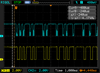
This one is different; it demodulated completely as expected/desired. Maybe because the AGC was still set up from the previous signal. This doesn't make me happy, though, because I like deterministic behaviour. But, it still suggests that the problem is tractable.
Byte 2:
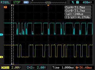
Wahh! Now the 2nd-4th bursts are merged. Well, still the rest of the signal is fine if I can safely get past the first three bursts.
Byte 3:
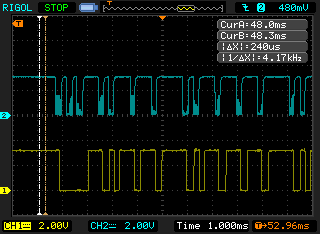
Grr! Now all three initial bursts are merged!
Byte 5:
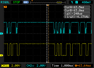
Now the 3rd and 4th bursts are merged. Hrmrmrmrrr!
OK, so what can I do?
Well, one thing is I can give up, and go back and implement the IR detector circuit in discretes. But I'm just too hard-headed for that. Plus, since the signal looks so good for the rest of the transfer -- just the initial burst is a problem -- I am more impelled to carry on. So I have two ideas:
- I can try to lock out the spurious transitions for the first 3-half-bit-times and then be careful about sampling the first burst period, and carrying on from there. This should be doable.
- I can log transitions, and decode backwards. In a perfect byte transfer, there are 15 bursts. The byte transfer ends with 3-half-bit-times of spacing, so the end of the signal should be very easy to detect. If I were to log the timestamps of all the transitions, and reliably detect the end, then I should be able to decode the signal in reverse, at the expense of the storage of the transitions log. I believe I will have enough RAM to spare to support such a log.
OK, because I like to do things the hard way, I am going to make option '2' first attempt. I think it will be fun, and I think it might even prove to be the most reliable way, given the limitations of the IR decoder. After I get it working, I'll probably make some sort test suite (which means figuring out how to program this HP28C). If it doesn't work out, then I'll be back at the drawing board on the detector.
Onward...
For now I am parked again until my Blue Pill boards come in. I went and ordered some more that ship state side, so maybe I'll get those next week. If I get some time before then, I might try implementing the decoder on a Nucleo board I have, since that core code would port to the Blue Pill anyway, but I do have several other projects competing for my time, alas....
 ziggurat29
Discussions
Become a Hackaday.io Member
Create an account to leave a comment. Already have an account? Log In.