-
Front Lights tested
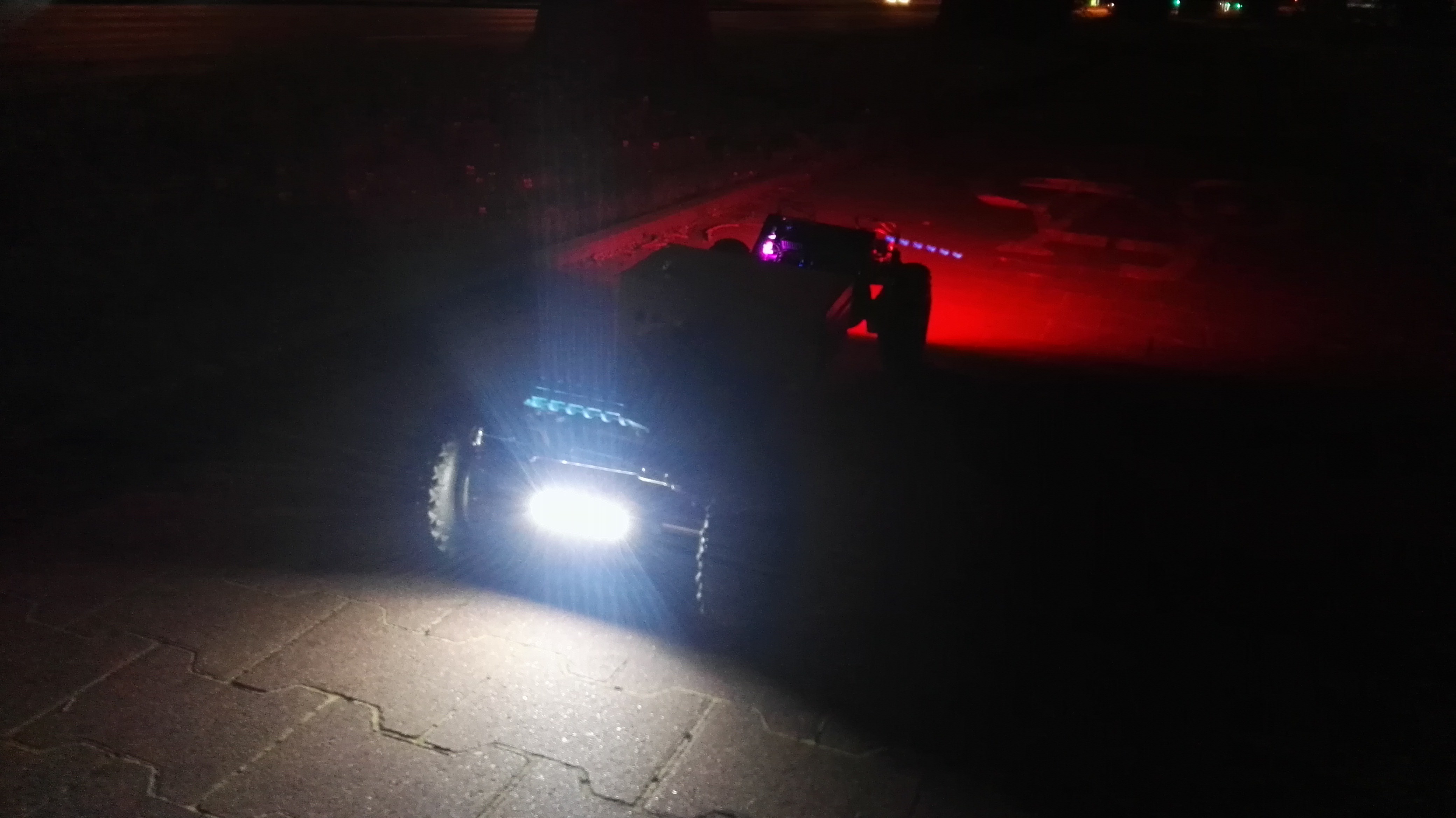
07/16/2017 at 06:00 • 0 commentsA few days ago the weather finally allowed me to test the board outside after dusk.
The test had 2 objectives:
1) test how the module performs, wheather it can be used to ride the board in complete darkness
2) see if designed mounting method is correct (e.g. no screws getting loose)
I covered around 10km (~6 miles) in the neigbourhood and first thing that I noticed is that now the board looks dope AF (I mean, it looked fine without the lights, but now it's even better ;) ).
![]()
Second observation is a bit less positive - angle of the beam produced is too wide, so the light quickly fades with the distance. Depending on ambient lighting (street lamps etc.) the visibility range provided by the module is only around 2 meters, which is definitely too short.
Two methods of solving this problem come to mind: using LEDs with narrower angle (currently used have 120deg... - my mistake) or building some kind of reflector to form the beam.
As far as mechanical properties go, I was pleased to see that the mount did just fine - nothing got loose and it was sturdy (so the light does not 'vibrate' when riding on pavement).
I created a short video showing the lights working in blinking mode:
The plan for now is just to enjoy the board and the summer. The Front Lights module has some flaws that can be fixed in version 2.0 (narrow angle LEDs, proper voltage regulation, better buck coverter design), so if I have some spare time on my hands in the future, I will work on FL a bit more.
-
Front Lights ready
07/06/2017 at 15:07 • 0 commentsToday I finished installing FL module.
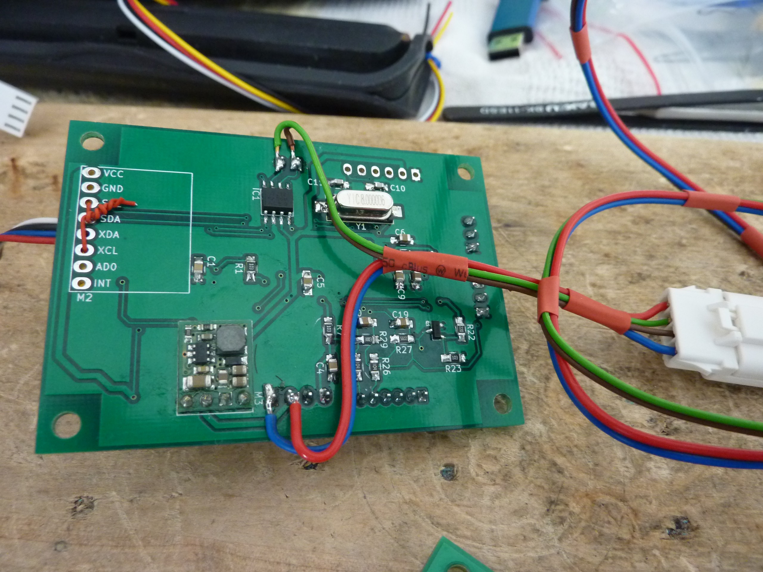
First, I changed voltage regulator from MCP1702 to MCP1790, so that now the module can be powered from 24V.
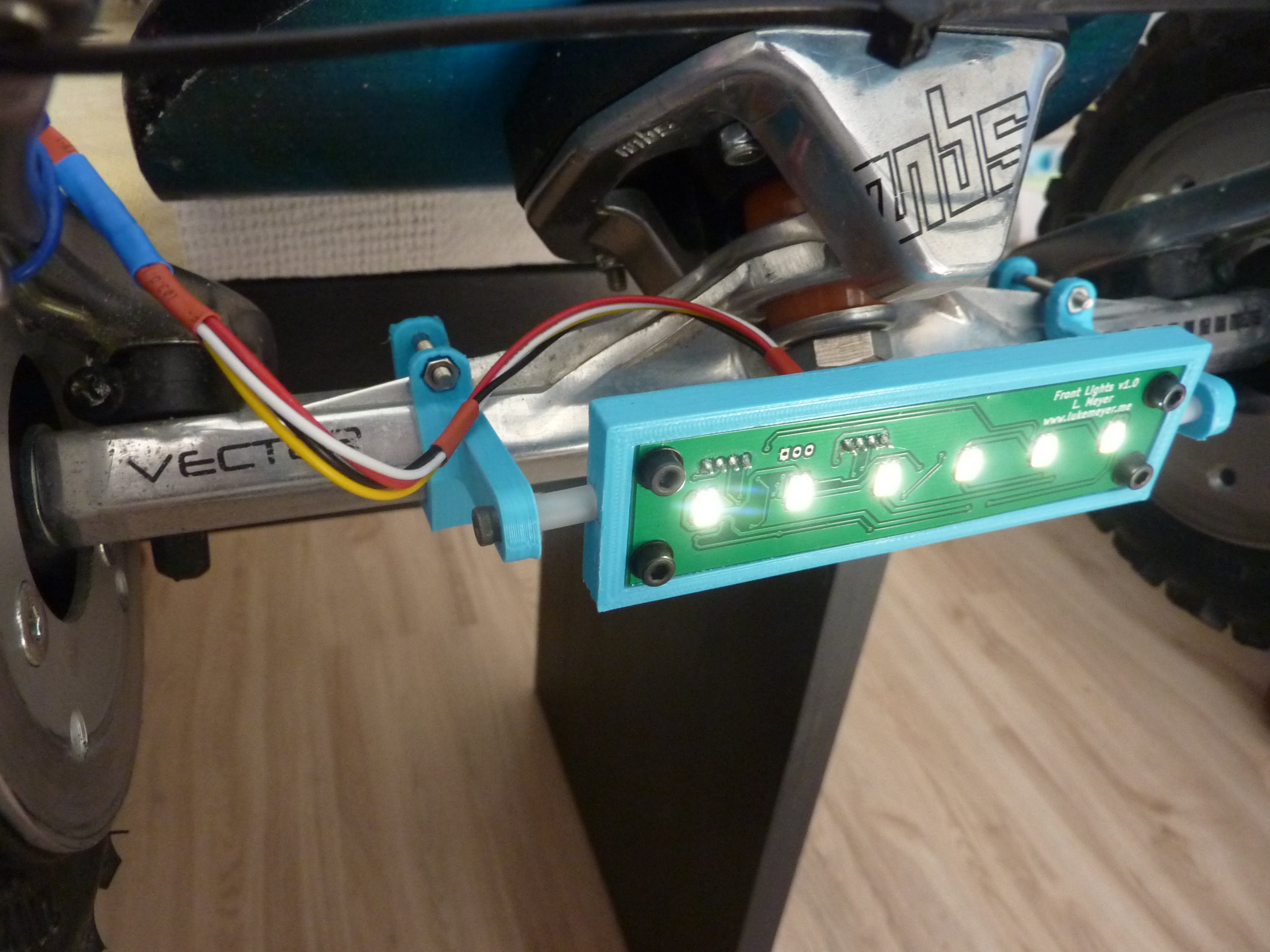
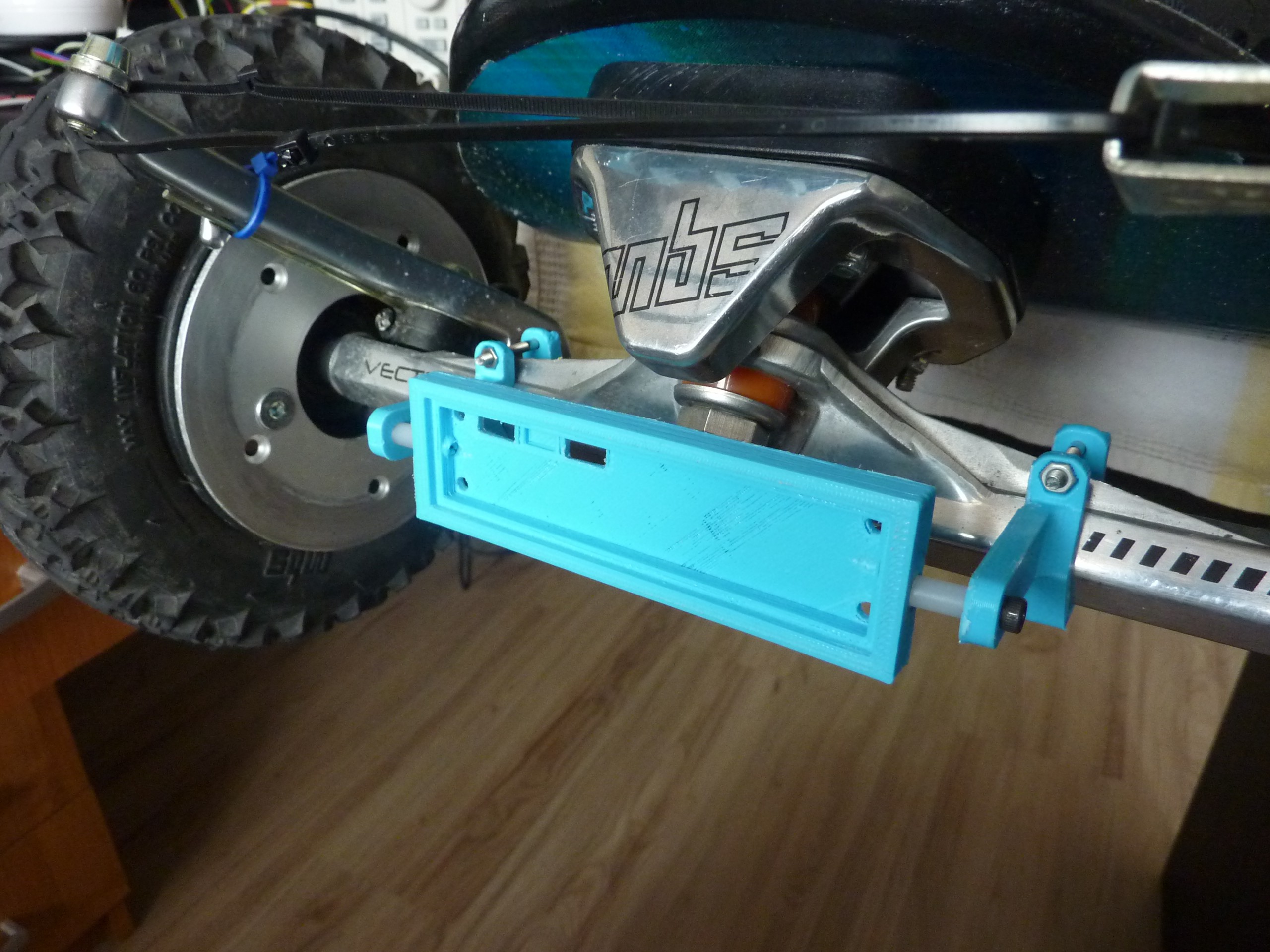
Then I installed the module inside its case:
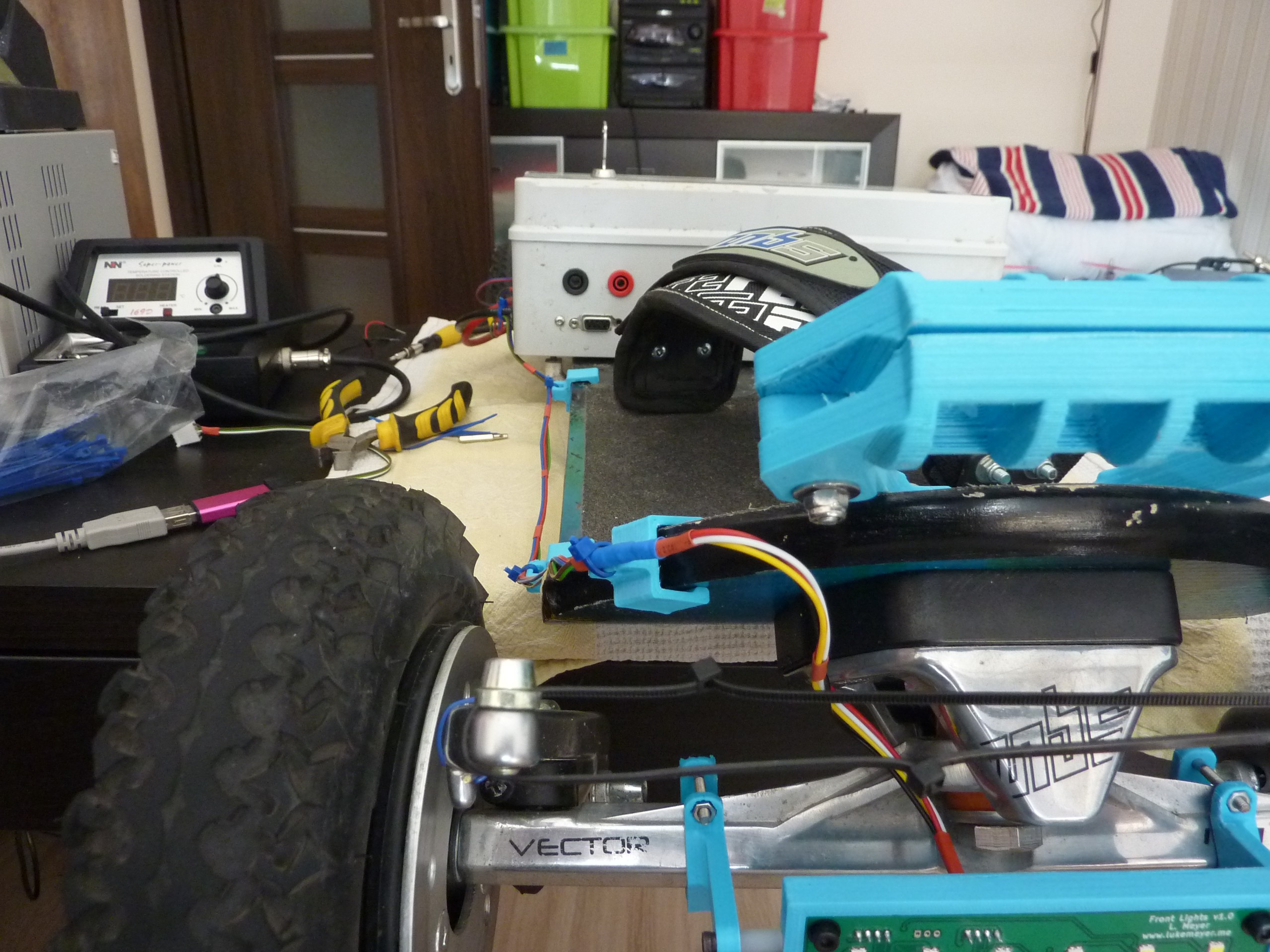
The last thing I had to do was securing the wires. I used 3D-printed wires holders and zipties:
Now the only thing left is testing the lights when it's dark outside :)
-
Firmware development + Front Lights case
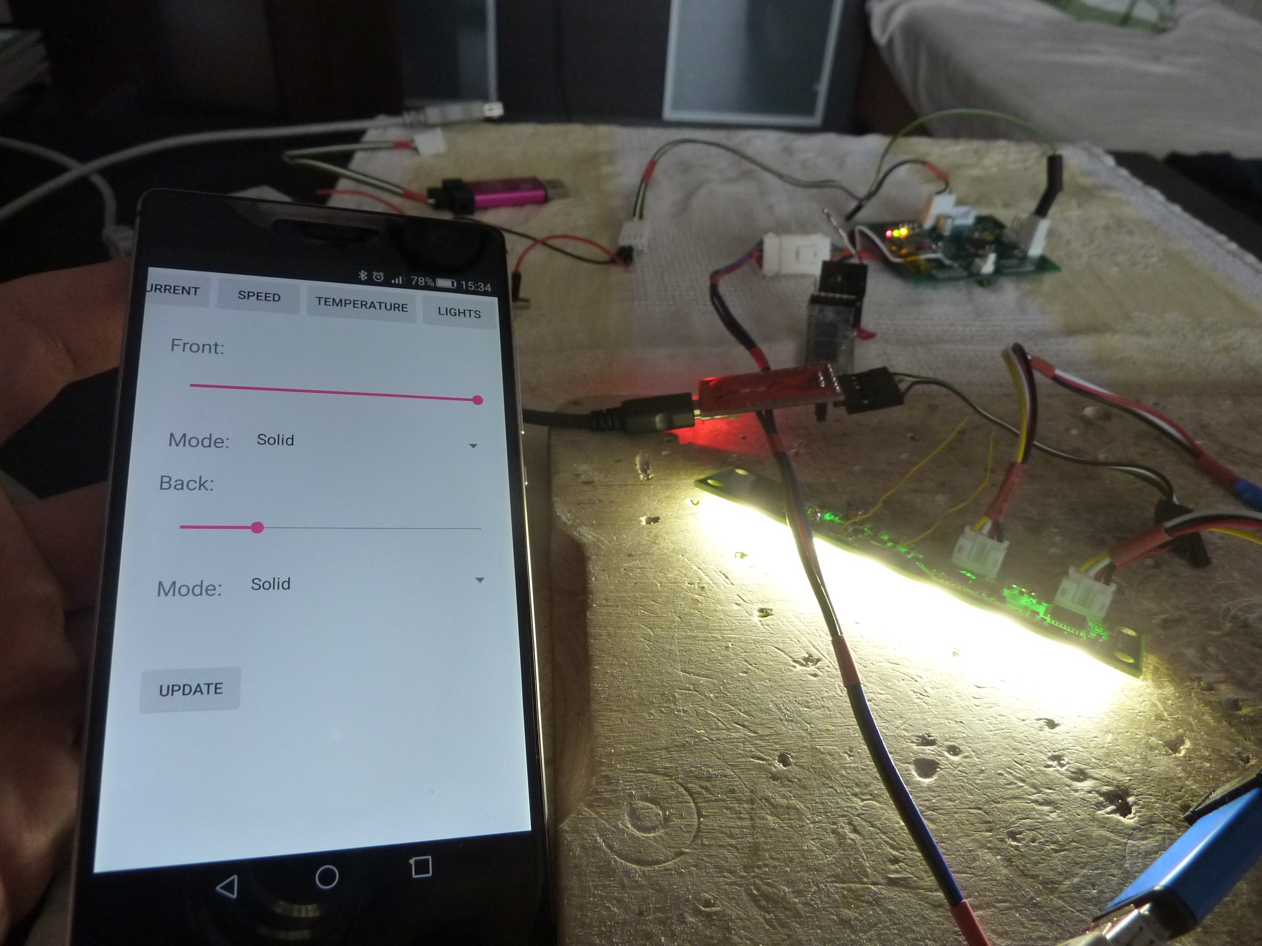
07/05/2017 at 16:35 • 0 commentsI modified Android application and Control Unit firmware so that front lights can also be controlled (brightness, blinking mode) via Bluetooth. Previously only rear lights settings were being sent from the phone. Now Control Unit receives all the settings and sends two CAN packets. One for Front Lights module and one for Drivers Unit Controller. I updated the firmware (for CU and FL) on GitHub.
I also printed and assembled Front Lights module case and mount. I discovered an error in my design. Mounting element screw collides with part of the truck and I cannot move the mounts too close together, so for now I had to use 6mm bushings to compensate for this error.
This mistake can be easily fixed by making the mounting element arms a bit longer (so that the crew is a little bit higher relative to the truck).
Next step now is replacing the voltage regulator on Front Lights module. I didn't check the maximum input voltage of used linear voltage regulator (used to provide 3V3 voltage for MCU), which turned out to be 13V. The on-board voltage is nominally 22.2V (max 25.2V), so I had to find a replacement. I found another chip, but in different package (first one is in SOT-23, the new one i SOT-89), so a bit of tinkering will be necessary.
After replacing the voltage regulator I will carry out final assembly and testing and the Front Lights module should be 100% ready to use!
-
Front Lights wiring
06/28/2017 at 14:32 • 0 commentsToday I prepared the wiring for FL module. The cable consists of 4 lines: 2 for power (+24V) and 2 for CAN.
The cable from FL is routed to case in the middle of the board. When I was designing Control Unit I didn't anticipate that I'll have to provide power and CAN lines for another board. So now I had to come up with a way how to 'steal' power and CAN from CU board. Fortunately the connectors are through-hole, so I ended up with a pretty elegant solution.
I added MOLEX ditto connector (close to CU), so that I can disconnect CU and FL boards when needed.
Now wiring is complete and I can move on to firmware modifications, so that I can control front lights mode and brightness via Android app.
-
Front Lights module assembly
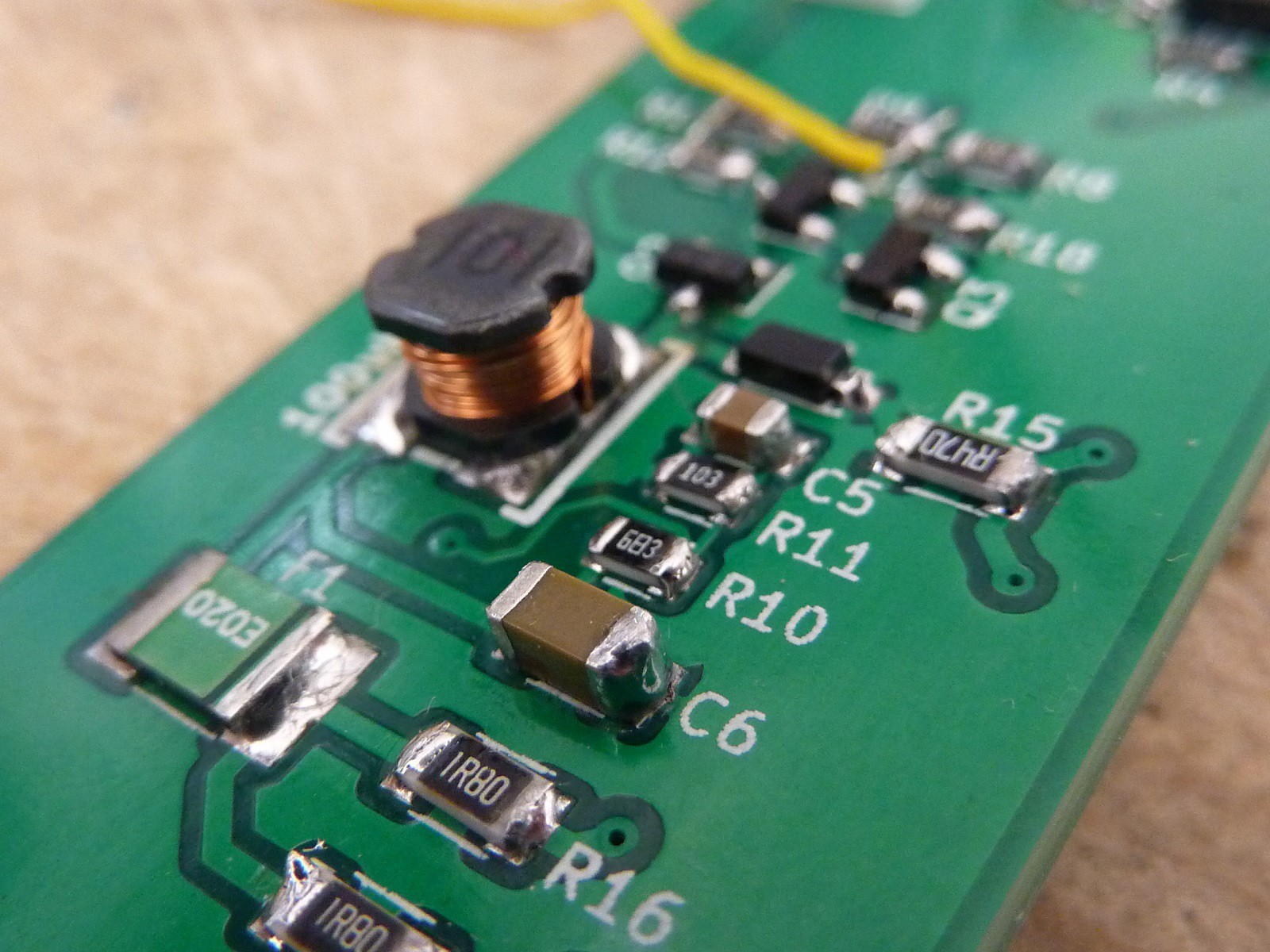
06/27/2017 at 15:22 • 0 commentsIt's time to fire up the soldering iron and assemble some electronics.
Front Lights module is supposed to be mounted in front of the board and provide light, so that others can see me after dark (and I can see what's in front of me as well, cool).
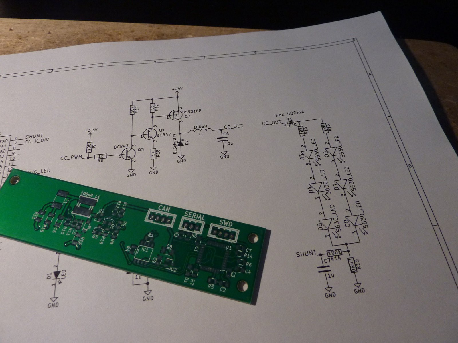
My idea for this module is to create closed-loop current control system using buck coverter and MCU.
The MCU would measure the current flowing through the LEDs and adjust PWM duty cycle to achieve required current. I hoped that maybe I'd be able to implement model predictive control (MPC) (using DMC - Dynamic Matrix Control). Of course predictive algorithm would be an overkill in this application, but would be a pretty nice educational excercise.
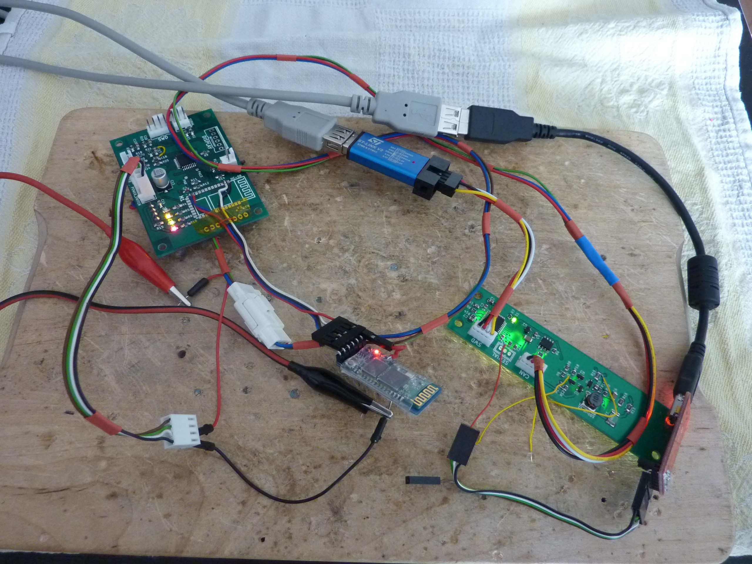
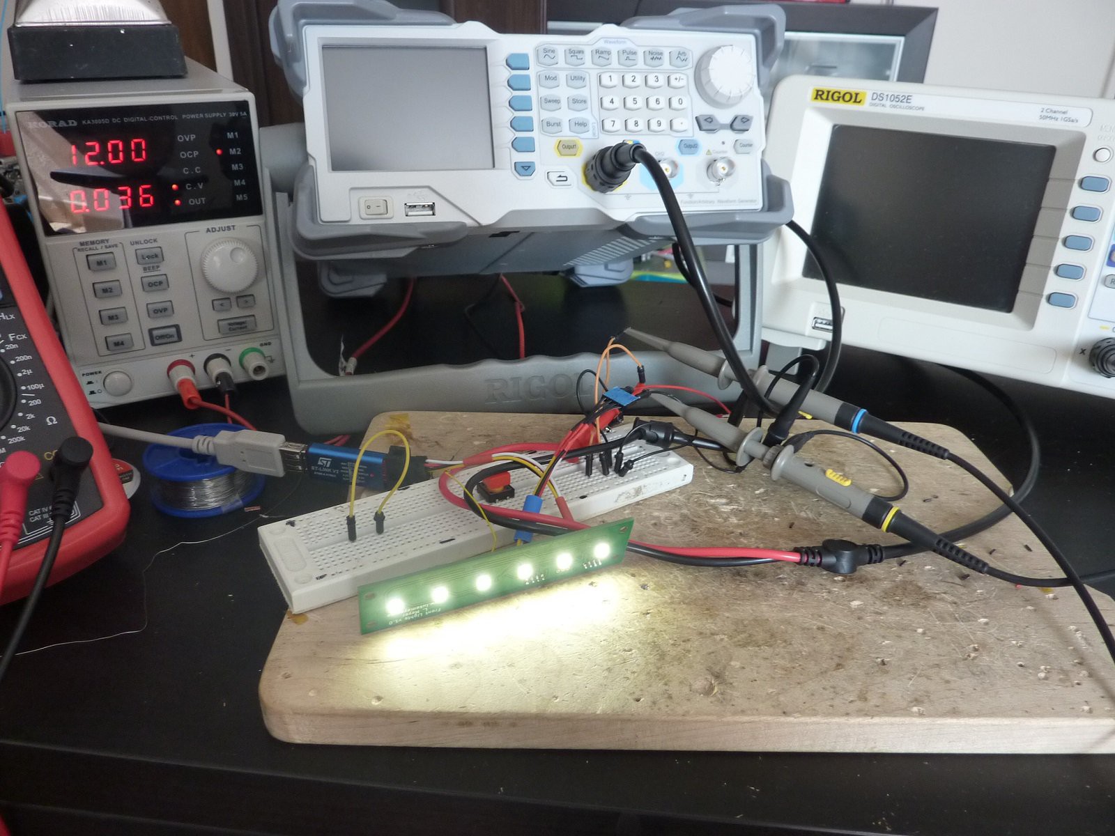
So far I've assembled the circuit and tested it in open loop mode (no current measurement, just setting pre-programmed PWM duty cycle).
Code is available on GitHub: https://github.com/Lukaszm94/Eboard_FrontLights
Currently open-loop brightness control is implemented, as well as blinking modes. Now I need to modify Control Unit software, so that front lights brightness and blinking mode can be changed via mobile app.
Electric mountainboard with CAN bus + Android app
Mountainboard with BLDC motors, open source drivers, CAN bus communication, custom Android application and cool lights.
 Luke
Luke