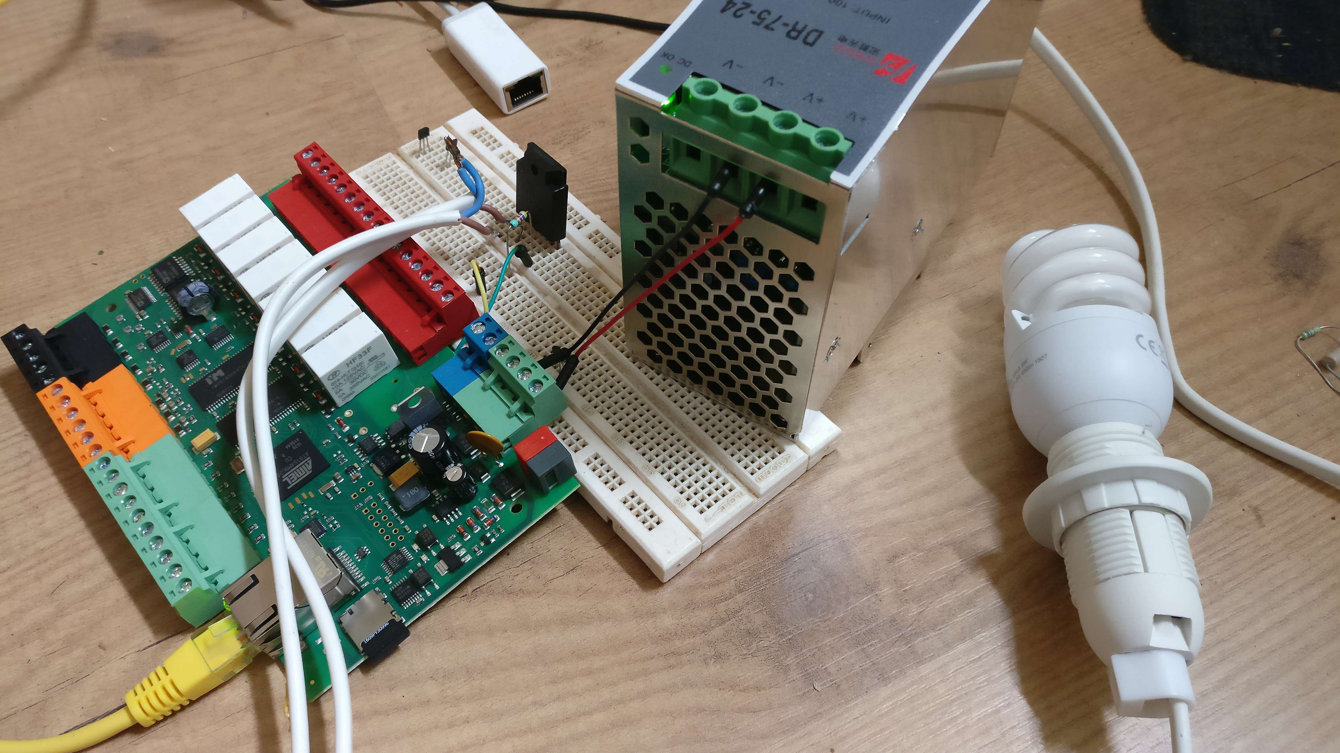
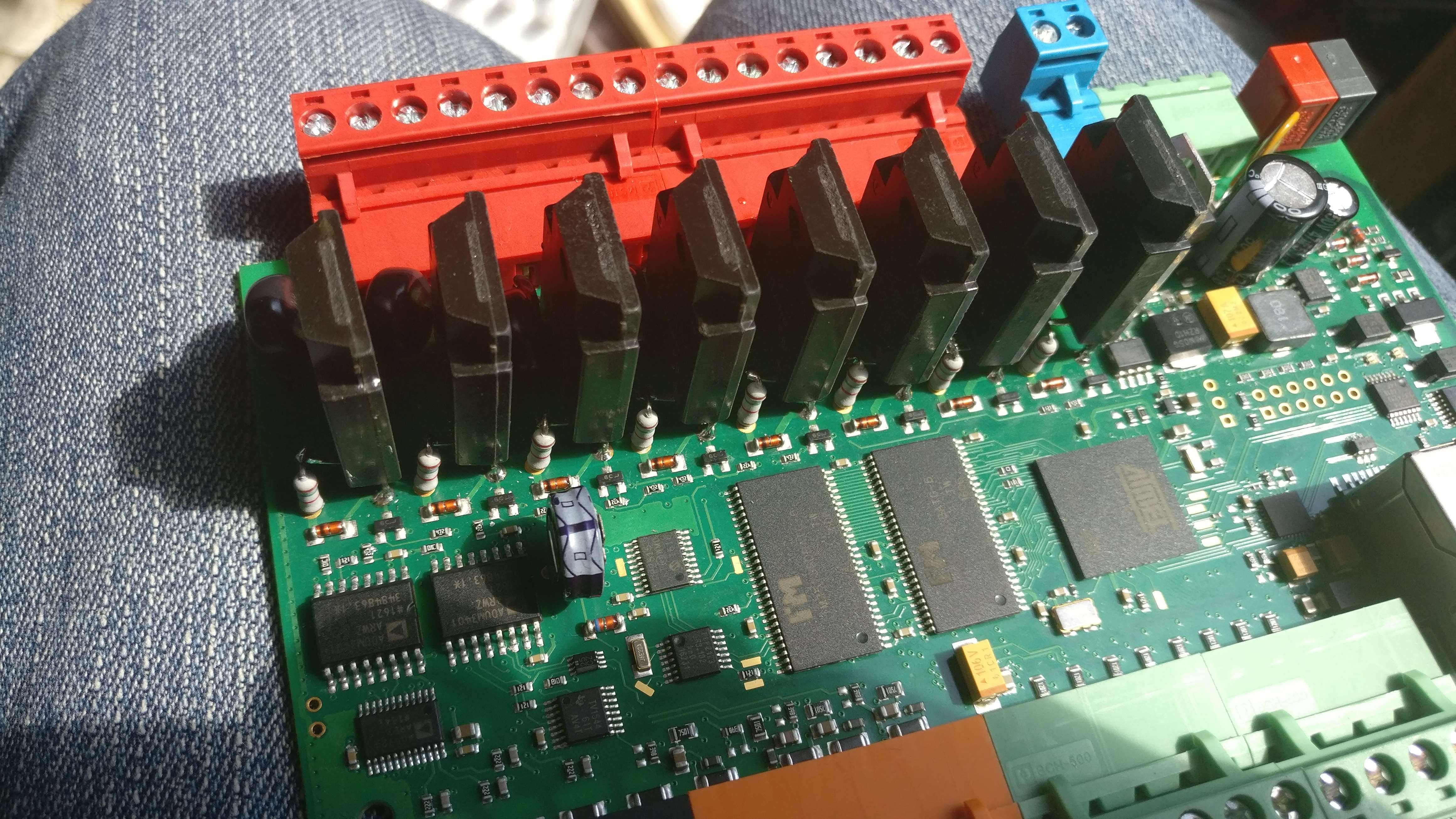
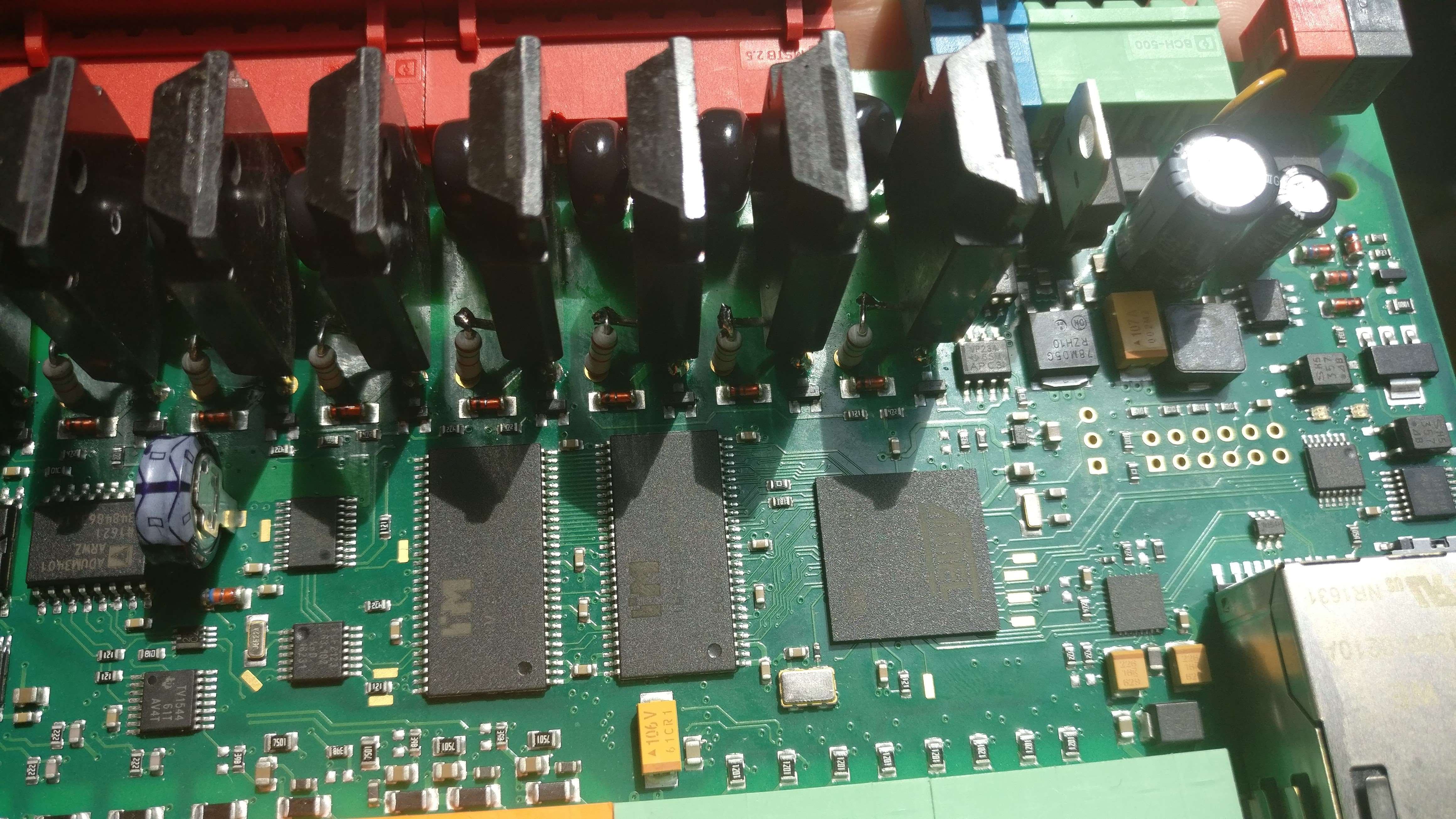
I bought a Loxone and I am happy with the product. Good software, plenty possibilities and easy to use. But I hate the relay outputs. The click-clack sound is annoying. That was my main reason to replace the relay with solid state relay (SSR). SSR is a semiconductor part and has no moving parts. This is also the reason why a SSR will last longer than a normal mechanic relay. But because it's a semiconductor, it's more sensitive to ESD (electrostatic discharge). This will be solved by adding a varistor.
Advantages:
* Current output up to 16A
* No mechanical switching parts, the makes the SSR also better for environments with flammable gasses
* Zero crossing switching reduces signal noise
* Short switching time vs mechanic part
* No contact bouncing
* No sound from SSR.
Disadvantages:
* It's not possible to switch a small analog signal. Possible with a mechanical relay.
* The SSR only handles the AC OR DC voltage it is made for.
*The SSR heats up@large Amps
Components
8×
S216S02
Switches and Relays / Solid State Relays
8×
MFP1-1K5
Resistors (Fixed) / Metal Film, 1k5, 1W
8×
ERZE08A511
ESD and TVS Suppressors / ESD and Transient Voltage Suppression (TVS) Varistors
1×
House electric wire 2.5mm²
Before we start.....I can not be held responsible if anything goes wrong during or after the modification procedure. I presume you have soldering experience and please only proceed when you are sure that you can safely modify your unit.
You can open the Loxone by gently apply a flat screwdriver on the side to release the plastic tab on the side. The mechanical relay are the white square things next to the red connector.
You can remove the relay by using soldering wick or a desoldering iron or using hot air. I first added some leaded solder tin to the solder connections I want to desolder. The leaded solder tin has a lower melting temperature and makes desoldering more easy. Please be careful with desoldering the relays with hot air, because the PCB is double sided assembled and it's easy to desolder components that you don't want to unsolder. I used hot air and also a normal soldering iron with a desoldering pump. Be careful in removing the relay. Don't apply to much mechanical pressure to remove the relay, because you possibly will rip the solder track from the board if you do.
Please remove the solder from the relay holes on the PCB. From the desoldering process there will be small pieces of tin on the PCB. Remove it gently from the board with a soft brush.
2
Soldering the SSR on the board
The normal mechanical relay are controlled by a BC817 NPN transistor. The relay coil (24VDC) will be replaced by a resistor and the LED from the SSR. I bought cheap SSR from Aliexpress (https://www.aliexpress.com/item/FREE-SHIPPING-S216S02-S216S02F-S216-TO3P-4-5PCS/32802165635.html ). This SSR can handle up to 16A (max) and is almost pin compatible with the normal relay. First we have to determine the resistor that is in serie with the SSR LED. The Led voltage is 1.2V. The minimum trigger (on) current is 8mA, but please take a current greater than the minimum current to ensure that the SSR goes into the a stable "on" state when the 24V is applied. I choose for a current of 15mA. The resistor value is : 24-1.2/15mA = 1520R. I choose for a 1500 ohm resistor. The dissipated power is P = U*I = U * U/R = U²/R = 22.8²/1500 = 0.347W. This is a little bit more power than a normal resistor can handle, so I took a 1W resistor (http://nl.farnell.com/welwyn/mfp1-1k5-ji/resistor-1w-5-1k5/dp/1565355).
We solder the 1k5 resistor on the + coil connection. the other side of the resistor goes to the + of the LED of the SSR. The - of the SSR LED is connected to the - coil connection on the board. The AC connections of the SSR are connected to the AC connections on the PCB.
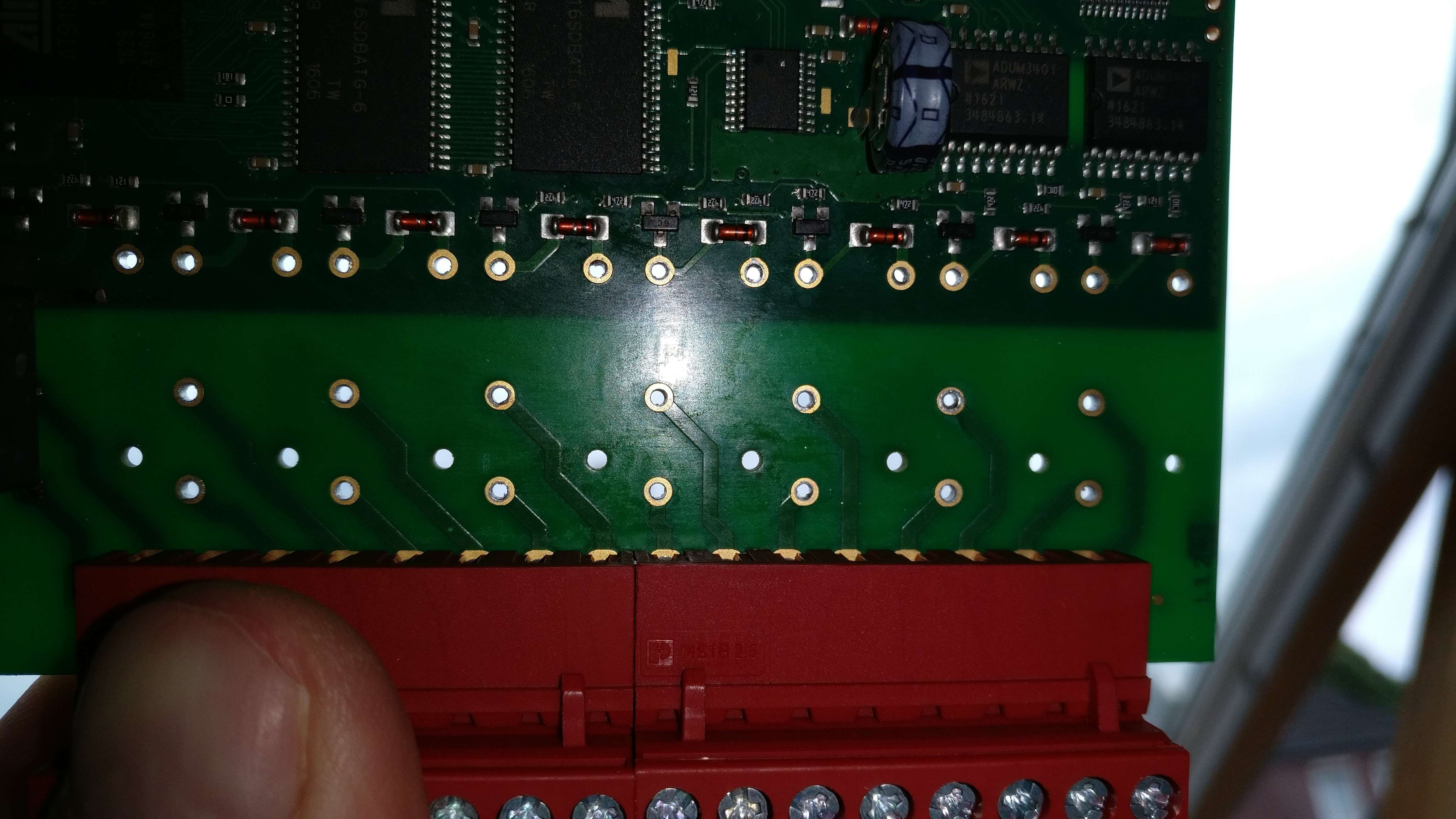
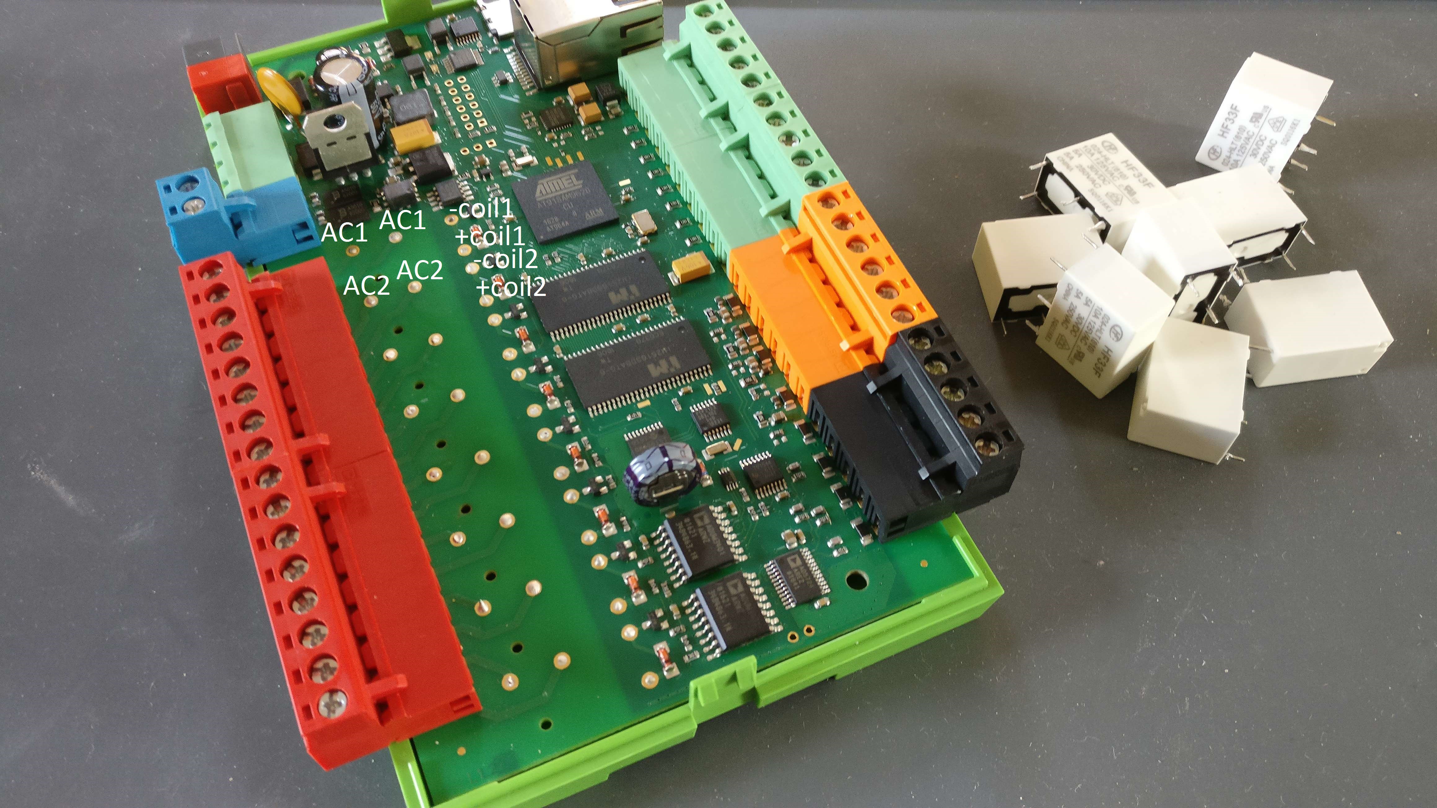
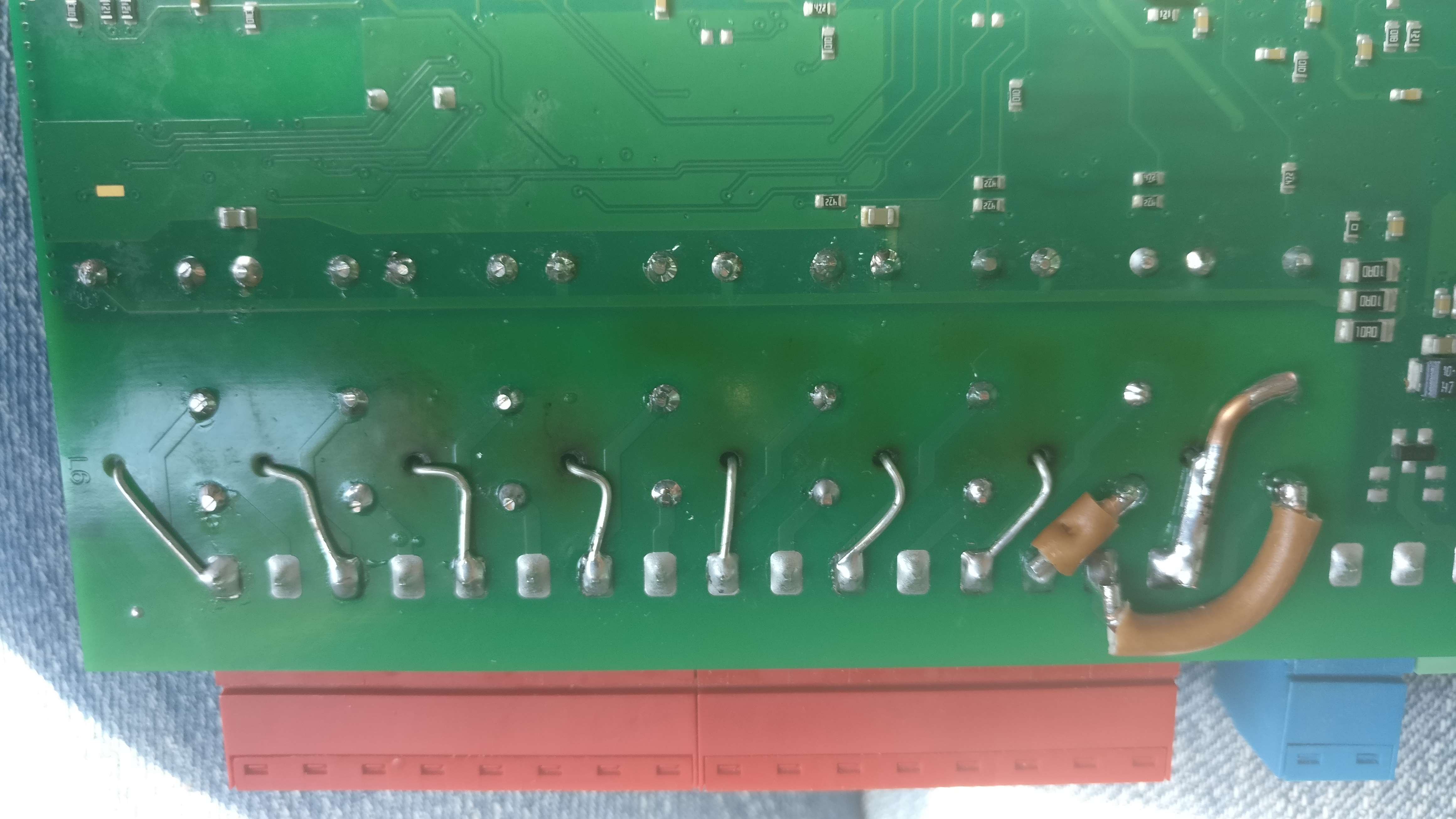
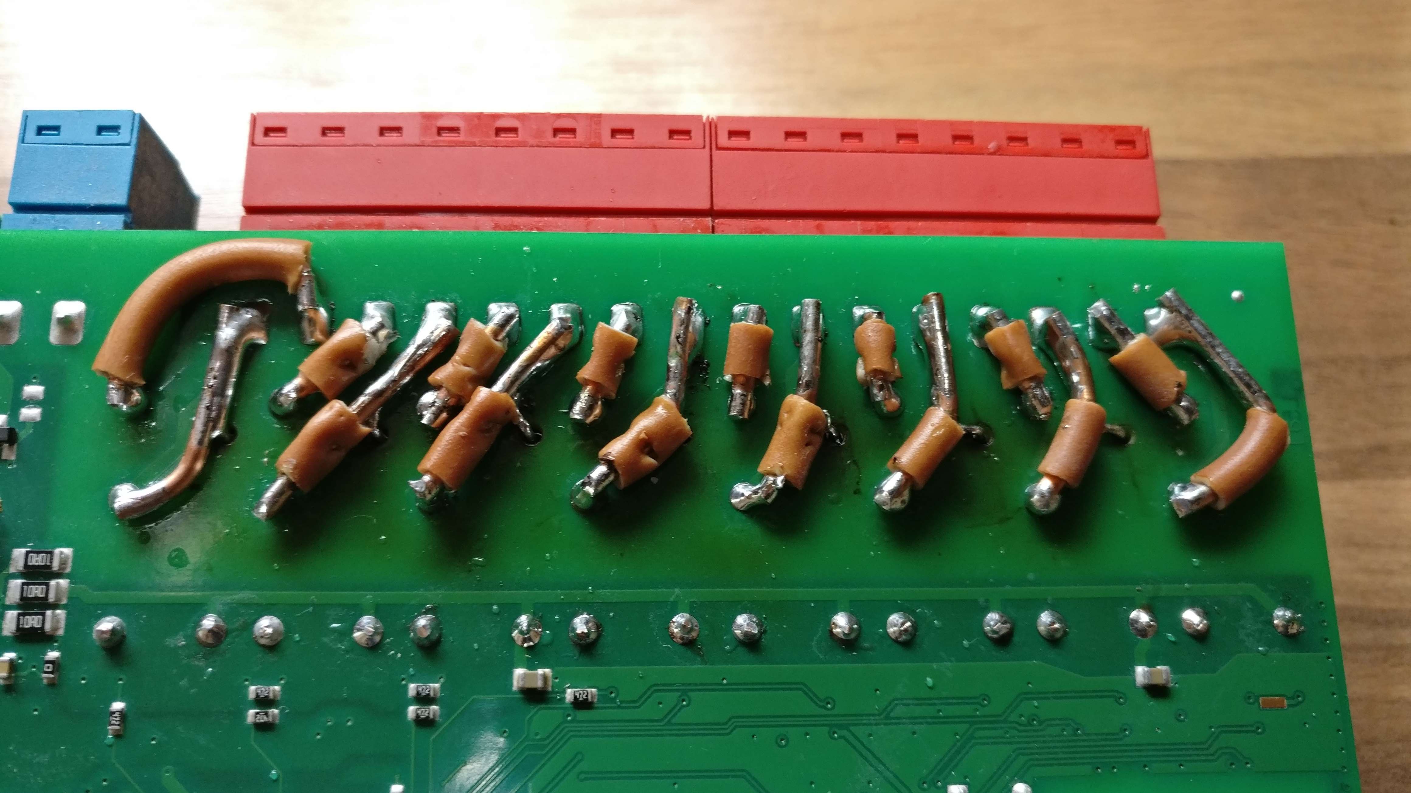
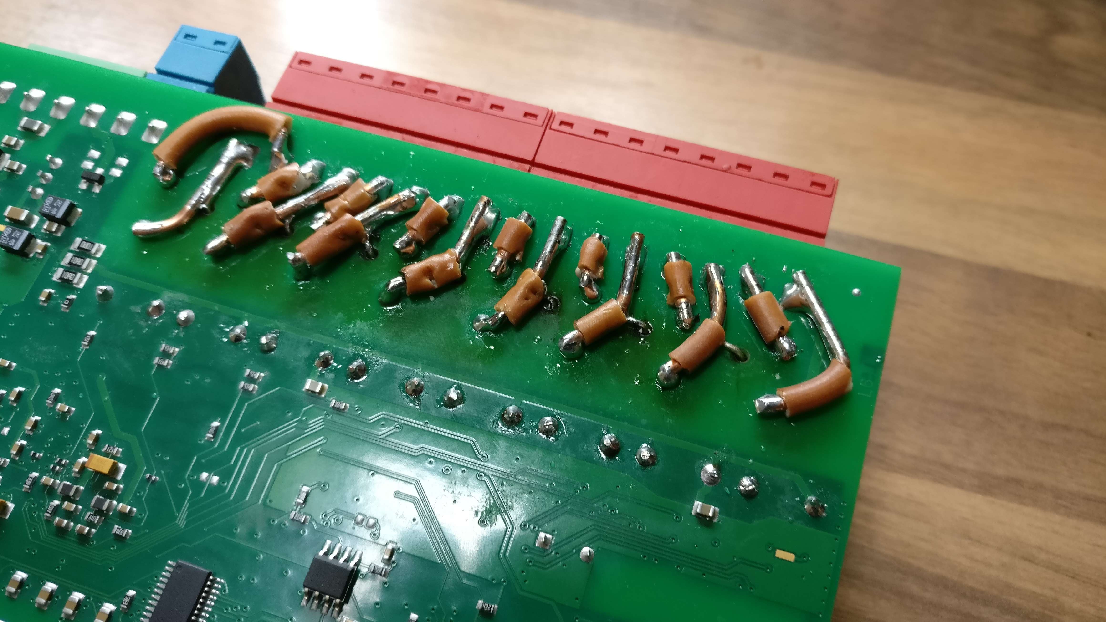
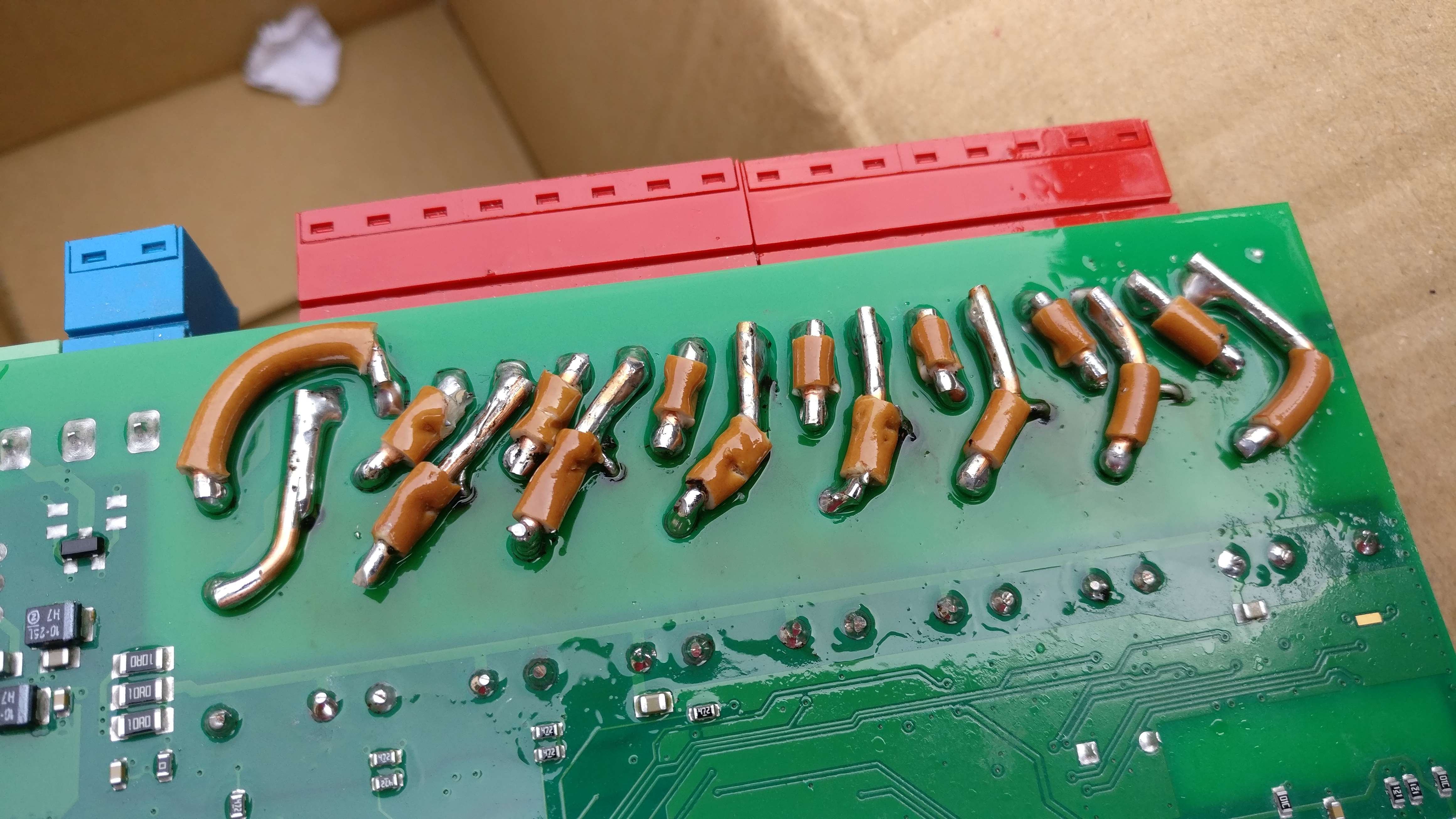
You can place the varistor on the board after you have soldered the SSR and 1k5 resistor. I ordered a big varistor that can handle more joules energy. If you have a small and flat varistor you can solder it directly on the bottom of the PCB on the AC connections of the red connector. I ordered this varistor (
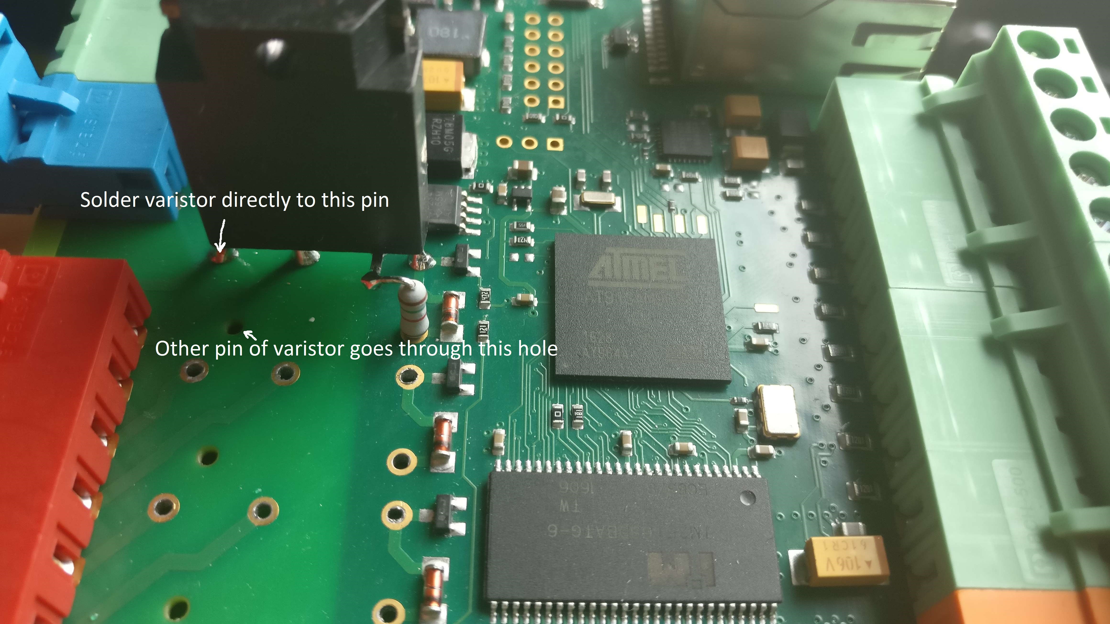
http://nl.farnell.com/panasonic-electronic-components/erze08a511/varistor-large-surge-transient/dp/2291796) and this is how I did it....
3
Upgrade the PCB to handle currents up to 16A
The normal tracks can handle up to 5A and are not able to handle 16A. The PCB tracks are not able to handle this current, so we have to make it possible to handle 16A. I used 2.5mm² house wiring cable on the bottom to enable larger currents. Make sure that you have some distance between the AC connections to avoid shorting the connections and/or discharging between connections. Keep the connections as short as possible and follow the PCB tracks with the 2.5mm² wires on the PCB. The current will mainly go through the 2.5mm² wire because the current will follow the way of the least resistance (that is not the PCB track!).
As a last step I have put a plastic coating on top of these connections (red kontakt chemie "plastic 70").
what would be the advantages for SSR in this application (switching low power led lights, sunshade motors, electrical heating). Are there also disadvantages?