 Before heading into the electronic designs I'd like to go over the mechanics of the second prototype and the changes made. I think it'll clarify some of the demands put on the electric designs I'll be discussing later on.
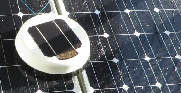
As you can see to the right, I've been having quite a lot of fun trying it out.
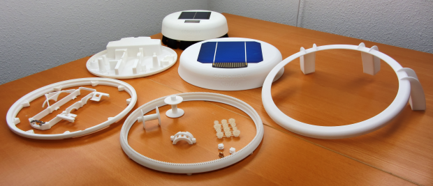
Lets start with the new parts (with prototype 1 in the background):


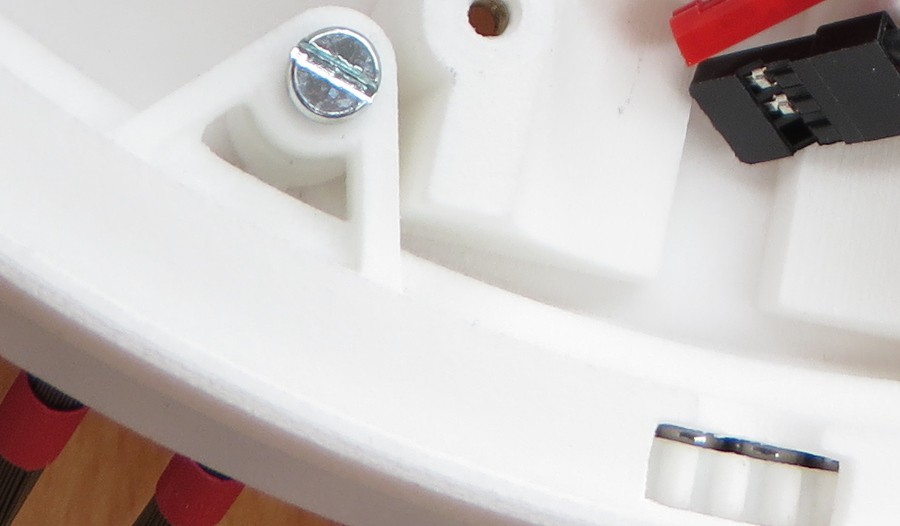
The main reason for doing this is that, while the previous bearing design worked very well, it was a real pain to assemble. The split design allows me to just drop in the bearing balls, instead of many minutes prying them through the small opening.
With the split design the bearing is still nearly completely sealed, only the drive gear has an opening (which will be shielded in production models, but allows for much easier part exchange here).
The top shell is now just an empty shell, there is a separate piece to clamp down the internals. This makes life a lot easier in both assembly and stress on the outer shell.
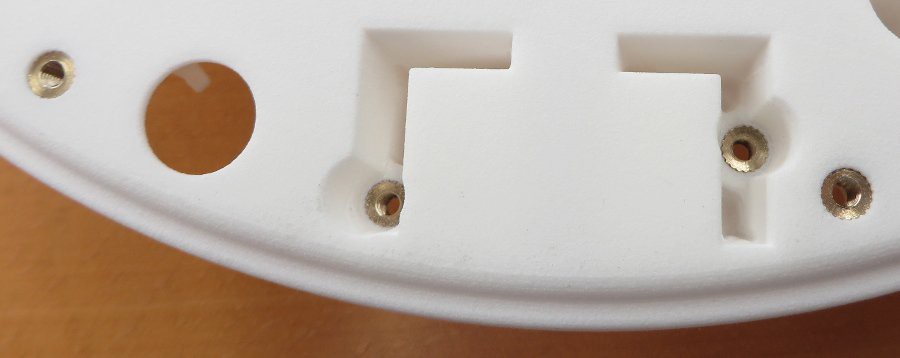
If you'll be doing a lot of taking things apart and putting it back together, get some of these:
They are sold by the 100 on eBay, named 'Metric Thread Brass Knurl Nuts'.

Discussions
Become a Hackaday.io Member
Create an account to leave a comment. Already have an account? Log In.