-
V4: Mosfet attempt
08/19/2014 at 15:43 • 0 commentsEven though I am without any type of receiver I figured I'd try to make the control board smaller. I bought mosfets with the intent of making two h-bridges. This would decrease power consumption and make everything smaller and easier to hide. Stupid me bought the wrong mosfets. I bought 8 N enhancement mosfets with too high of a switching voltage. So between the fact that half should have been P and the fact that they are too high of a switching voltage, I screwed up. I should have stuck to the plan of the wireless router and stuff, so next revision will be that.
-
V3.5 Big Oops
08/19/2014 at 15:29 • 0 commentsSo the Remote control receiver has a "turbo" function. I figured I could tap into it and install horns. I thought what could go wrong? Apparently everything since I fried the chip trying to solder. I was originally hoping that V4 would be solid state using mosfets and such, but now it seems that since the control system needs attention I will be shifting my priorities to that. So time to make it WIFI controllable. My Idea is to use the serial port of a router and connect it to an MSP430. We will see how that goes.
Purely for posterity here are the horns I was planning on installing.
![]()
-
V3: IN ACTION
08/19/2014 at 15:11 • 0 commentsI finally remembered to take video of it functioning. This car is faster than it looks. The second Video has a nice lesson on why to mount things. AKA things will be made much smaller in the next revisions. This was a quick dirty functional toy.
-
V3: Now With Steering
08/19/2014 at 14:52 • 0 commentsSteering was definitely an issue on this project. Skid steering was too unreliable and too unpredictable. It took me a few days to figure out the solution. The easiest way was to remove the steering wheel and attach a drill, simple enough!
![]()
This is intended only as a temporary solution since I can't exactly fit a child in the car the way it is. Either way, drive-ability went up exponentially. It became way more fun to drive. The modifications to the wiring couldn't have been more simple. I put the two rear motors in parallel on one set of relays and the drill on the other set of relays. From there I had to turn the switch on the controller 90 degrees and it was done.
![]()
-
V2: Wheels in Motion Without the Chasing
08/19/2014 at 14:37 • 0 commentsThe title stems from the fact that this revision added wireless functionality. This is the first money spent on this project. A $7 remote control toy car was purchased and torn down for its precious wireless ICs.
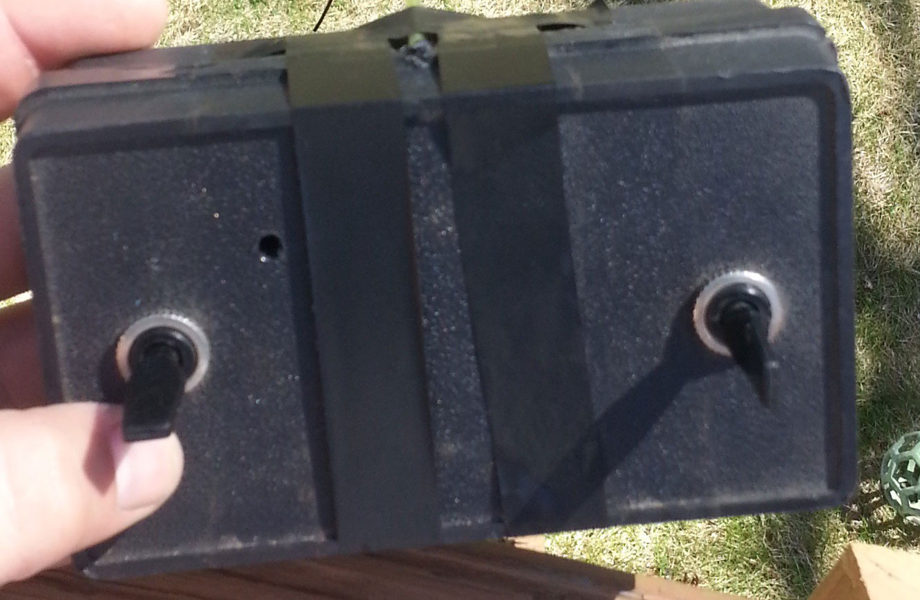
Basically the parts from the RC car replaced the CAT5 cable. The transmitter was jammed inside the DPDT switch controller, and the receiver was attached to the SSRs. This was easy to accomplish. The following is the controller from a newer revision, the only difference is that the right switch is turned 90 Degrees
![]()
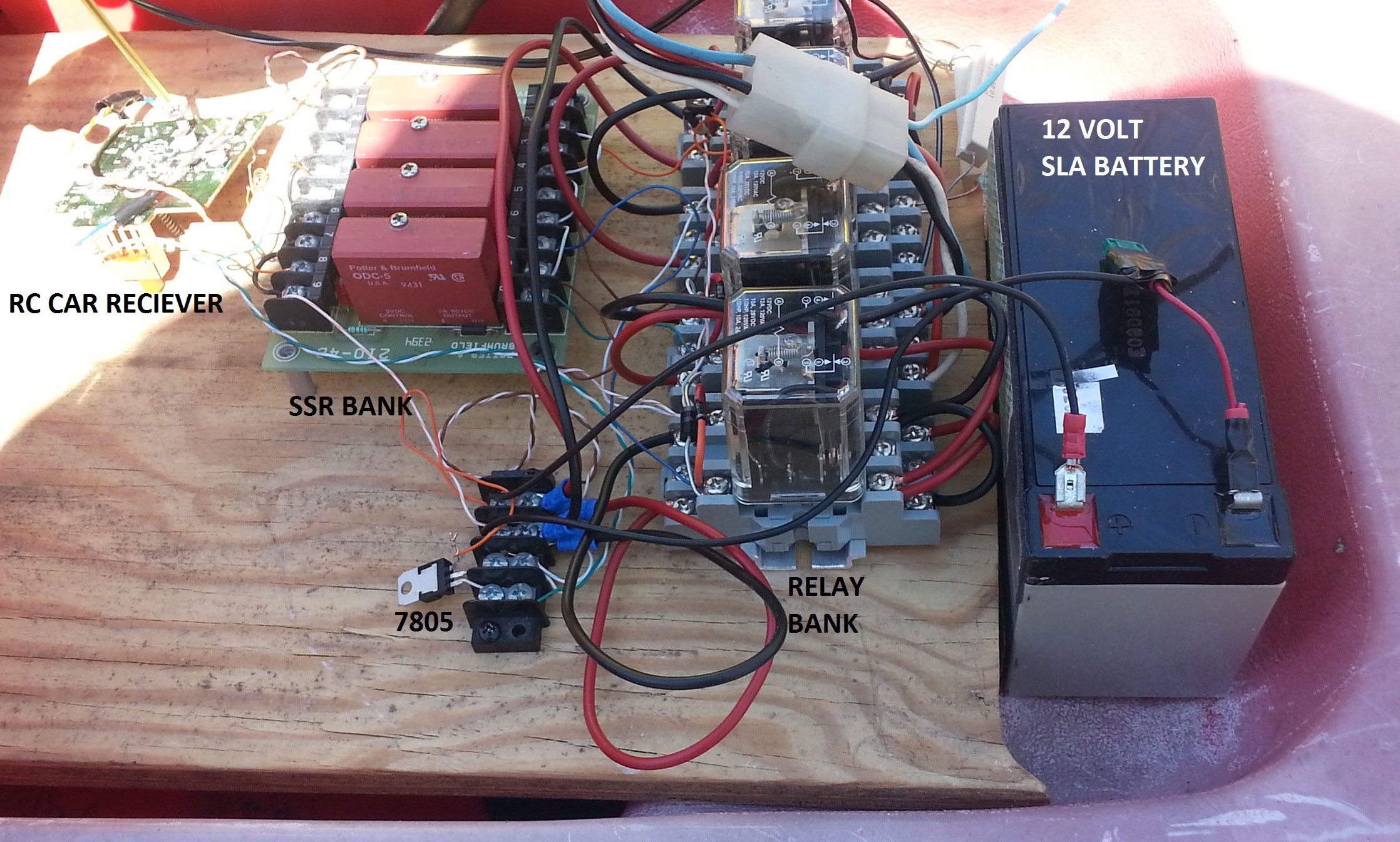
The power for the RC car was designed to use 3 AA batteries. Close enough that 5 volts won't fry it. In comes the 7805 regulator to power it. The motor ICs on the original car were more than enough to power the SSRs. Thus creating revision two. It is basically the same schematic as revision 1 so I will not be redrawing it. The following is the control board installed in the car.
![]()
-
V1: Wheels In Motion
08/19/2014 at 14:21 • 0 commentsThis version was mostly to test the functionality of the toy itself. This version was done completely using found parts no purchases were made in this revision.
For this revision I wanted to keep everything simple and make sure that it moved. Since it had independent rear motors, I figured the easiest control system would be to control them independently. I later found out that the front wheels have a little too much grip for reliable control. For this log I won't be writing up any schematics unless someone asks due to the simplicity of it.
The control was achieved through a 12V SLA battery, 4 3PDT relays, 4 Solid state relays, a few diodes, a few feet of cat5 and 2 DPDT center off momentary switches. I know that these parts are overkill, but it was what was laying around.
Basically each motor had two relays, One for direction and one for power. Each relay was then activated by one SSR. The power fed to the controller of the two switches. The switches then fed into the SSRs. To make the motor go forward one of its relays was activated, for reverse both were. This version was purely a test. Things will eventually progress to more complex technology.
Remote Control Power Wheels
Taking a toy Power Wheels and making it remote control. Making improvements as time, money, and availability of parts allows.