-
1Important up-front notes.
THIS MATTERS. DON'T SKIP IT.
- Many project assembly instructions are written for a generic audience and include step-by-step component ordering. If you've done enough projects, you probably have your own routine for placing things, and you probably don't pay much attention to that part of the assembly instructions. This board has sizeable components on both sides of the board, and the positions overlap. If you do some of the things in the wrong order, you may find that you can't get at the lands to solder later components. If you are experienced, you can visualize it yourself and do whatever you want. If you are less experienced, I recommend using the order that I enumerate.
- The overall power supplies for the project are the type of 12vdc wall warts you can find many places, and they power the LED strips themselves. In addition, one of the inputs (the "A" input) feeds into an adjustable power supply component mounted on the main board. It powers the microprocessor and everything else other than the LED strips. Once you apply power to the assembled board, that adjustable power supply will be immediately feeding power to the microprocessor board. It is therefore important that you adjust the power supply to have an output 3.3vdc before placing it on the main board. The microprocessor board says it will operate off of 3.0 - 3.6v. If you try to adjust it after it's on the board, you may be unlucky and damage the microprocessor.
- Once things are assembled, there will not be enough room to plug a standard micro-USB cable into the microprocessor board to upload firmware. (It gets power a different way.) There are a few possibilities for dealing with that, from most convenient to least (in my assembly, because I'm paranoid, I did all of them except "d"):
- Load an esphome config to the board ahead of time. It doesn't matter too much what the config is as long as you get far enough to do OTA updates.
- Install a micro-USB right-angle adaptor so that the USB port is can be reached.
- Put the microprocessor board in a socket so it can be removed for updates.
- Create a custom micro-USB cable that has a connector geometry that can be used in the limited available space.
- I urge you to do the dry fitting in the next step. If you don't, you might regret it.
-
2The Dry Fit
The vertical spacing (that is, from the main PCB surface upwards) for the microprocessor board and the display board is tight. Due to the natural variation in otherwise standard parts obtained from far-flung sources, the dimensions of your header pins might be slightly different from the ones I have. It is therefore important that you "dry fit" the parts together so you can see if you need to make any adjustments. Dry fitting means putting the parts together in their actual positions but without applying any solder or anything else that you can't undo. Read over the next few steps and experiment with your actual parts to make sure things will be OK.
What follows are my suggestions for the way I did mine. You might need to do some variation.
Because of earlier problems (of my own making) leading me to need to desolder the microprocessor board, I've opted to use a socket this time. The microprocessor board has 20 pins on each side, and the sides are 900 mils apart. It's difficult to find a DIP socket that size. Instead, I used a low-profile 40 pin socket (2x20, 500 mils wide), but I snipped it down the middle so I could mount the left and right sides separately. There is a photo of it in a later step. If you choose to use a socket, be sure that it will allow you to insert standard header pins into it.
Speaking of header pins, I did not want the pins from the microprocessor board to be protruding too far out of the bottom of the board. They might interfere with the power supply. I also did not want the microprocessor board standing too high off the top of the board. It might interfere with the mounting of the display board. One way to resolve this is to trim off the long ends of the header pins after they are placed. I've done that before, and it tends to look a bit ragged. Instead, I found some shorter header pins. They're almost exactly 10 mm long (not quite 400 mils). Normal headers are another 2-3 mm longer. One way to buy them (and the way that I discovered them) was to shop for Adafruit Short Feather Male Headers (https://www.adafruit.com/product/3002) or Short Male Header Kit for ItsyBitsy (https://www.adafruit.com/product/4173), which are also available from various 3rd parties. We're not lucky enough that they come in 2 sticks of 20 pins. Somehow you'll need to come up with 40 pins altogether. You could also buy the pins generically from normal parts suppliers. Many lengths are available off-the-shelf.
With standard male header pins on the display board and standard female headers on the main PCB, there was not enough vertical space to seat the display board without being in contact with other things. I obtained some longer male header pin strips, with an overall length of 17 mm. That was just about right, except the display board was still pressing on the battery connector on the microprocessor board. After removing the battery connector, I had enough vertical clearance, even with the micro-USB right-angle connector in place.
My final arrangement was:
- DIP socket rows soldered to the PCB
- Short header pins inserted into the DIP socket. I inserted the longer ends of these shorter headers into the socket.
- Microprocessor board resting on the plastic nubbins of the short header pins, then soldered on the top side of the microprocessor board. If you are using an optional right-angle micro-USB adapter, plug it in before soldering if you are not using a socket for the microprocessor board.
- Standard female header strips on the main PCB for the display board.
- Longer 17 mm male header pins on the display board itself.
-
3Headers for the display board
The display board will eventually be directly attached to the cover of the box that holds the project. We have to be able to detach the display board from the rest of the components (to do the initial attachment to the cover, and in case of any additional work on any of the components). We'll fashion sockets out of header pins of both genders.
Before you do any soldering, you should do the "dry fit" described earlier. You might want to use longer than standard male header pins. Then come back here and do the soldering.
Solder male header pins to the display board. For reasons of physical geometry, you don't want pins protruding above the surface of the display. Insert them from the other side of the board, with the short ends going through the holes and the display board resting on the little nubbins. There is a set of 4 male headers on one end and a set of 14 male headers on the other end. When I bought my display boards, the came with the 14-pin header strip already in place. If you choose to use longer male header pins, you will have to desolder those first.
![]()
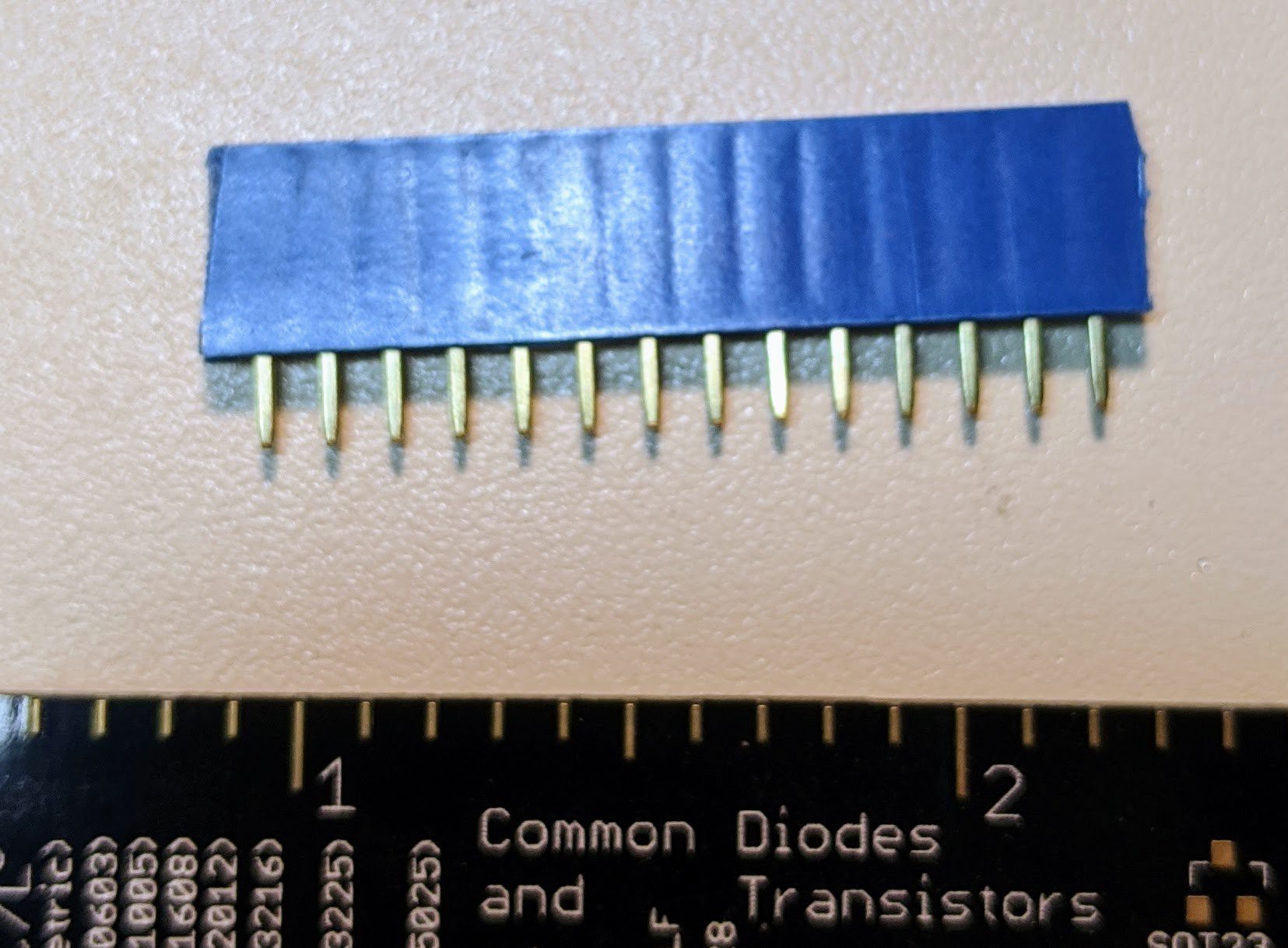
Photo A. 14-pin Female header socket strip Solder female header sockets to the main PCB. There is a 4-pin female header on one end and a 14-pin female header on the other end. You may find it useful to have the display board's male header pins inserted so that the female header socket strips stand up straight while you are soldering them.
When you are done with this part, it should be simple to gently place and remove the display board without bending any pins.
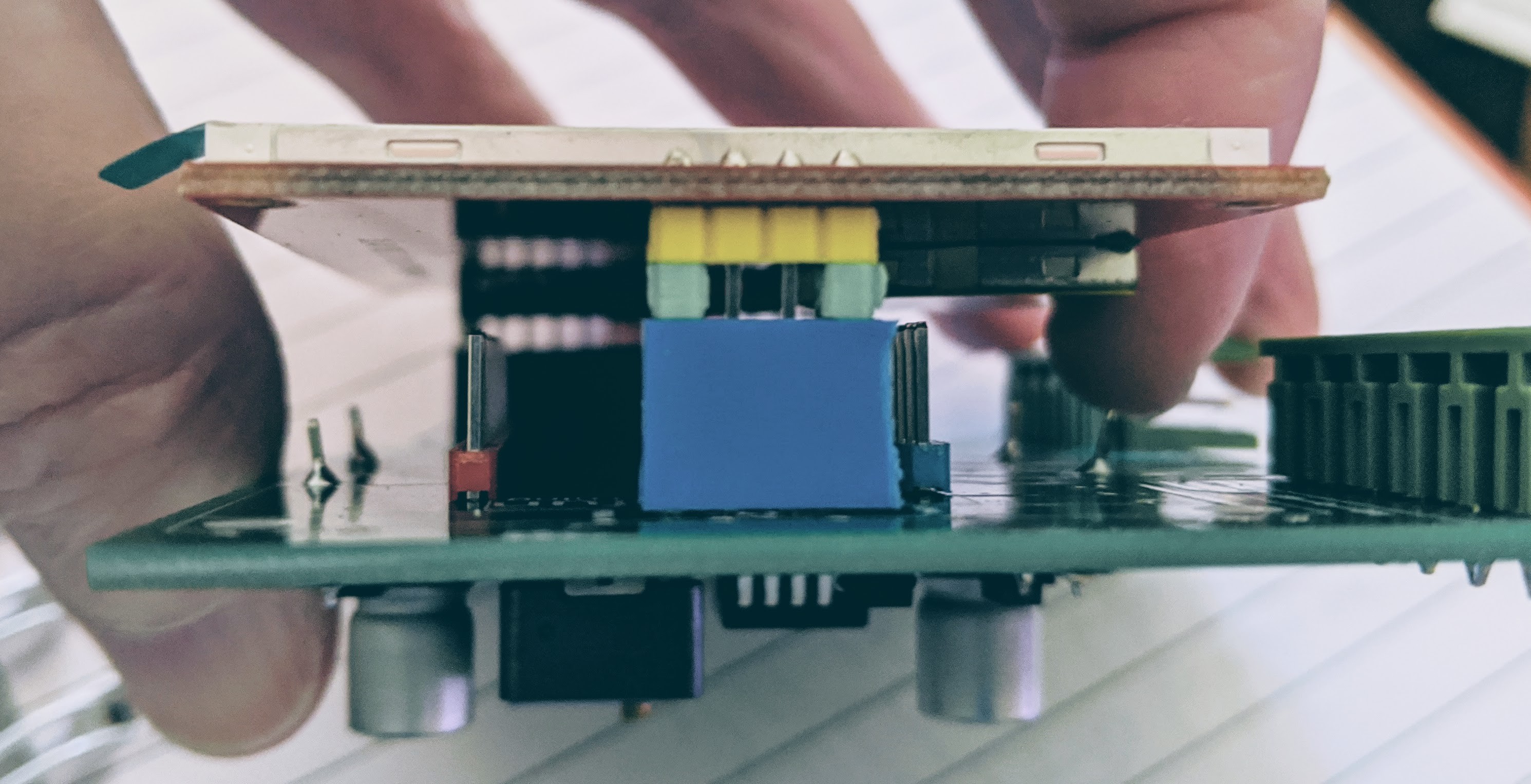
If your "dry fit" showed you that you needed more clearance for the display board, there are a couple of options. First, you could just get some longer male header pins. Most parts suppliers have them in many lengths; I also found some sellers of 17mm - 21mm male header pin strips on The Usual Auction Site. Second, if you just need a little more room with standard male header pins, you can make some stand-offs so that the male pins from the display board don't go all the way into the female sockets. Here's an easy way to do that:
- Take 4 standard individual male header pins. With needle-nosed pliers, you will be able to pull off the little plastic nubbins. (I do this accidentally all the time.)
- Slide one nubbin onto each male end pin on each end of the display board.
- Carefully insert the display component into the headers. There should be a little play in the female headers so that you can get both ends started; then push both ends at the same time to seat the display into the headers.
- The plastic nubbins acting as spacers will prevent the display board from seating all the way, and will also prevent the other parts from touching the back of the display. The display board should still slide in far enough to make good contact.
- Check with a multimeter that the solder blobs or pins from the display board on the top side actually are connected to the solder blobs on the bottom side of the main PCB. If there is not good contact, you will have to use a different approach.
![]()
Photo B. DIY stand-off spaces made from nubbins The photo was taken with a V1 board, so ignore everything except the green spacers between the male pins (yellow) and the female sockets (blue). If you don't really need to use the spacers, then don't use them. Things will be more structurally stable without them. Because I later switched to 17 mm male headers, I didn't need to use this technique after all.
-
4Sparkfun ESP32 thing
Unplug the display board and set it aside.
The next component to be placed is the microprocessor board, a Sparkfun ESP32 thing. You have some choices for how you mount this. I recommend that you do the dry fitting described earlier to make sure you have adequate clearance without the possibility of shorting anything. Also, for your own convenience, before you solder the microprocessor board in place, you should load an esphome image onto the Sparkfun ESP32 Thing to enable OTA firmware uploads.
If you want to, cut jumper "SJ2 PWR LED" on the microprocessor board to disable the power-on LED. It is not possible to disable this LED in software. For this project, we don't care about the current it draws, but it may be aesthetically undesirable. It will be hidden behind the display board, but an eerie red glow might still be visible.
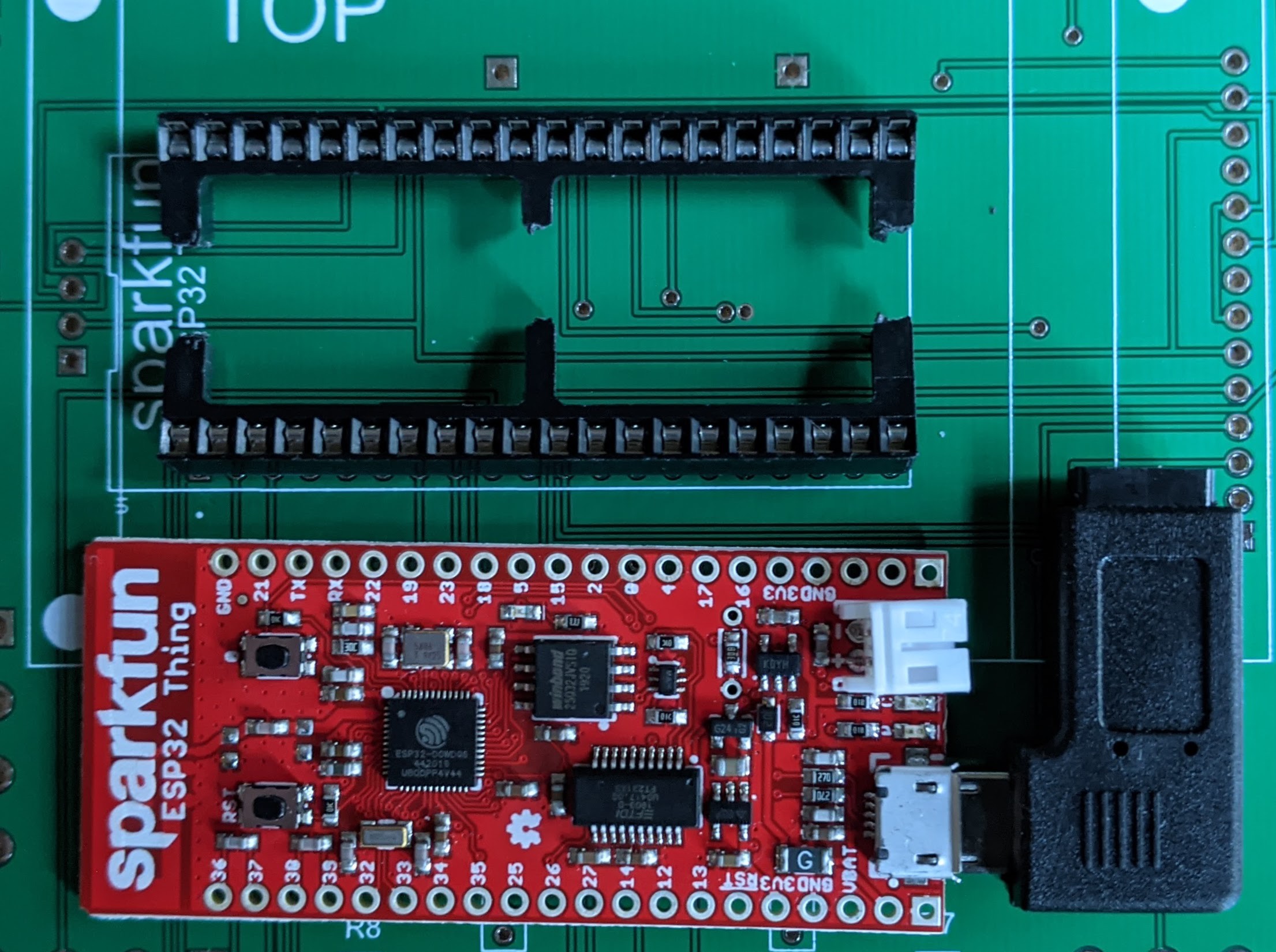
When you place the Sparkfun ESP32 thing, be careful of the orientation. The printed name of the board should match up with the printed name on the silkscreen. See Photo C, below. It's easy to get it mixed up because the USB and battery connectors make it seem like that's the main end of the board. Maybe it is :-), but look for the printed legend.
![]()
Photo C. Top of PCB and Sparkfun esp32 thing Photo C also shows the split DIP socket and a micro-USB right-angle adaptor plugged into the microprocessor board. You probably will not have room to add the right-angle adaptor later. I was lucky enough that the microprocessor board with the right-angle adapter that I had exactly fit in the space between the display board's two sets of headers. You can get an idea of that by looking at the lands in Photo C. (Photo C was taken with a V2 board, but the explanation still applies.) The large white connector on the upper right of the microprocessor board in Photo C is the battery connector. I removed it by prying it up and bending it back and forth until its two pins broke off.
-
5Adjustable power supply board
Stop! Don't solder this onto the PCB yet.
Because of the physical layout, we had to solder the microprocessor board onto the PCB first. When we apply power to the adjustable power supply, it will be immediately sending power to that microprocessor board. If the output voltage is not right, it can damage the board. Before adding the adjustable power supply to the main PCB, carefully adjust it so that the output is close to 3.3vdc. The microprocessor board says it will operate off of 3.0 - 3.6v.
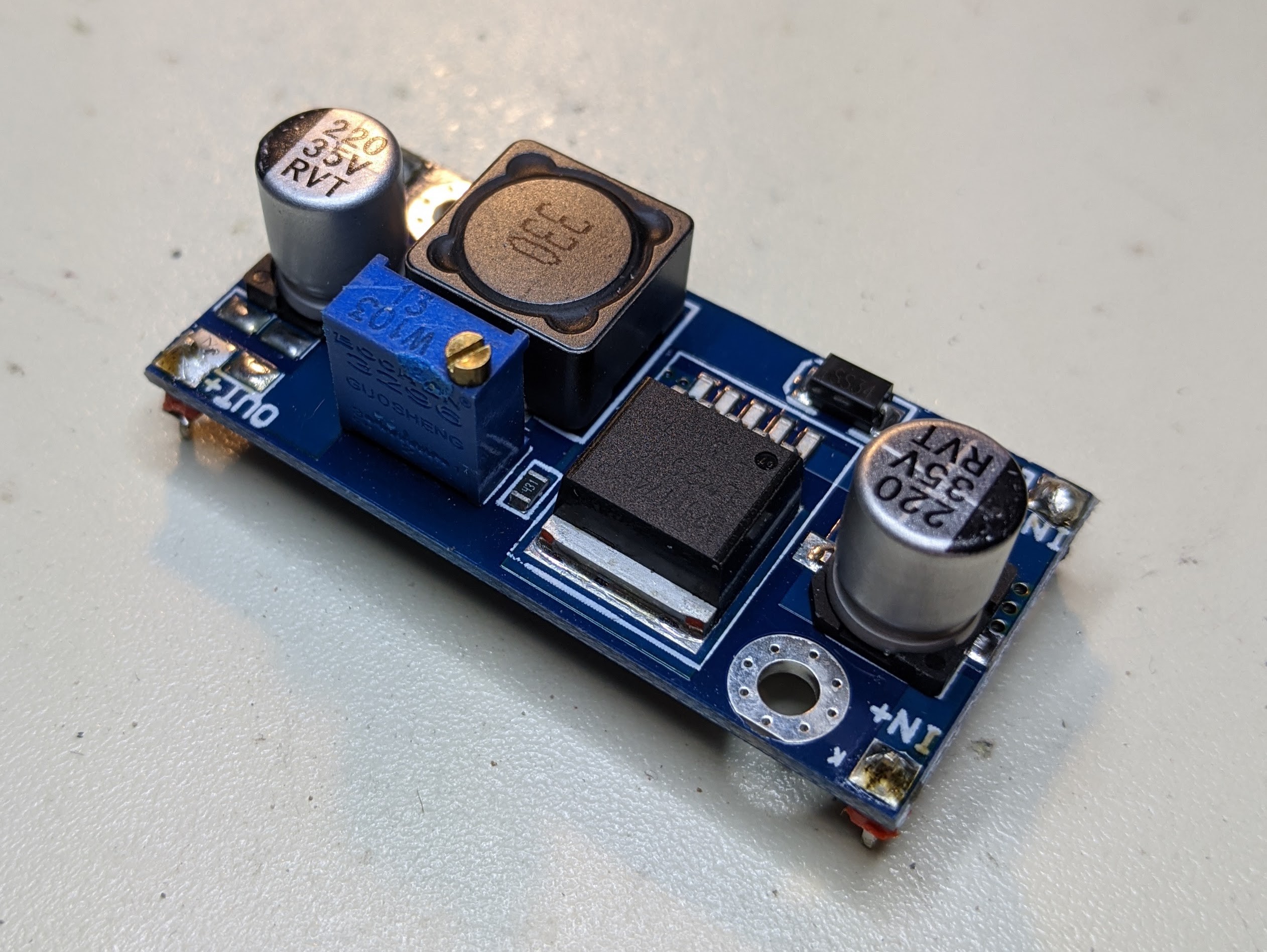
The adjustable power supply board has clear markings and places for handy pins for the inputs and outputs. Solder 4 individual male header pins at the corners of the power supply boards. You want the nubbins of the header pins to be on the bottom side of the board to act as spacers to prevent contact with the main PCB. I used red and black header pins for the positive and negative terminals, respectively.
Using whatever combination of alligator clips, bobby pins, paper clips, and baling wire that you can find, attach a 12vdc supply to the input pins. Positive should go to the IN+ pin, and ground should go to the IN- pin. Measure the output voltage on the OUT+ and OUT- pins. Use a small screwdriver to adjust the potentiometer on the board to get the output voltage close to 3.3vdc. This voltage will be applied directly to the 3.3vdc input voltage of the microprocessor board.
![]()
Photo D. Power supply board with pins in place When you have the voltage adjusted, you are ready to place the power supply on the board. It goes on the bottom side of the board, where you see its silkscreen outline.
- Notice that the pins from the microprocessor board are sticking out from the bottom side of the main PCB. As is, they probably don't interfere with the placement of the power supply board. If they do, or if they come close, clip off the ends of the pins from the microprocessor board. You can either clip them all off or clip just the central pins that overlap with the power supply position.
- Insert the pins of the power supply board into the marked holes on the PCB. (I found that I had to "stretch" the power supply pins outward very slightly to get them to fit into the board.) Double check that you got the orientation correct. Also check that no pins from the microprocessor board touch or come close to touching the power supply board.
- Solder the 4 corner pins of the power supply board in place.
-
6Terminal blocks
The board will have a total of 28 screw terminals for attaching various wires. It's 2 blocks of 6 pins and 4 blocks of 4 pins. They are arranged around both the top and bottom of the PCB. How you place the terminal blocks will depend in part on your personal preferences and on the sort of enclosure everything will fit into. And, because of certain overlapping physical realities, you should plan carefully for how you will place and orient things.
The design uses Euroblock connectors, also known as "Phoenix connectors", which consist of a socket, which gets soldered to the board, and an L-shaped plug with screw terminals. After attaching wires via the screw terminals, you can simply insert the plug into the socket. Sockets are available in both straight-through and right-angle configurations. If you are using the right-angle sockets, you can place them so that the plug is inserted from the outside of the PCB or the inside of the PCB. Regardless of which type of socket you use, the matching plug has only a single orientation with respect to the socket. If you are using the straight-through sockets, the orientation of the socket will determine which way the plug faces. It can be pretty confusing, so I recommend fitting all of the sockets with their plugs inserted on the board to make sure everything is reachable and nothing blocks something else.
My own preference was to use all right-angle sockets with the orientations as shown in Photo E, below. Wires from J1 and J2 then gently curve and feed down through the center of the main PCB board along with wires from the other connectors.
![]()
Photo E. Positions and orientations of all terminal blocks - Each grouping is marked with a silkscreen outline. Make sure you put each block on the side of the board with its silkscreen outline.
- Start by placing the 2 blocks of 6 pins. Solder the pins. The solder legs for the terminal blocks are fairly long, and you might like to clip them off where they will lie under 4-pin blocks.
- Place the 4 blocks of 4 pins. If you are using right-angle sockets, sockets J7 and J8 might have something that prevents them from being completely flat against the PCB. For that reason, you should solder them in place with the plugs inserted. Then you'll know that you have the correct angles to get the plugs in and out.
-
7Resistors
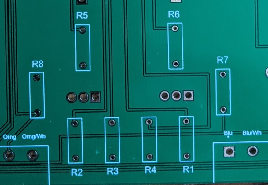
There are a total of 8 resistors in the design. There are 3 different values. On the top of the PCB, you can see the silkscreen outline for R1 through R8.
The values of the resistors are not critical as long as you use something in the same ballpark as the designed values.
- R1, R2, R3, R4: 100 ohms (LED current limiting)
- R5, R6: 300 ohms (MOSFET gate current limiting)
- R7, R8: 10k ohms (pull-ups)
![]()
Photo F. Resistors are not futile Solder them all in place and clip the excess leads.
-
8N-channel MOSFETs
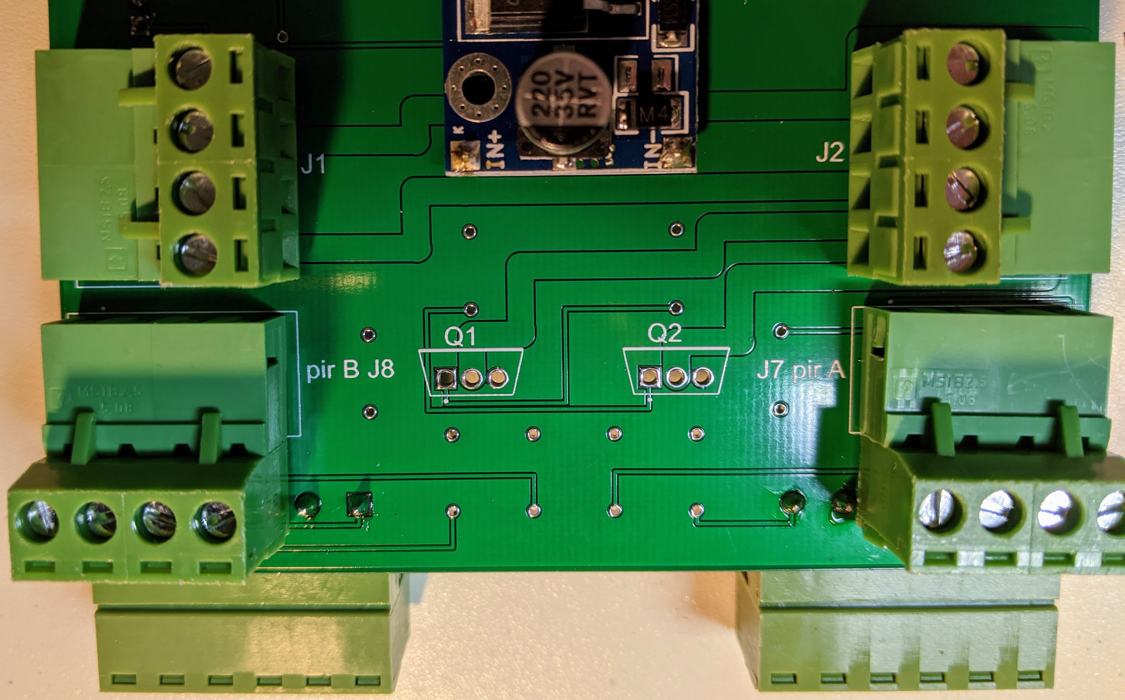
The only remaining electronic components for this main PCB are a pair of large transistors. They are N-channel MOSFETs. Both are mounted on the bottom side of the PCB, in the middle of the cluster of resistors, but on the opposite side of the board. It is important to get their orientations correct.
- When you are looking at the MOSFET, the metal tab with a mounting hole is the back side. Facing it from the front with the pins pointed down, the pin on the left is pin 1.
- On the silk screen look for Q1 and Q2. There are 3 mounting holes in a single row for each. One of the pads is square. That is for pin 1.
- Insert each MOSFET from the bottom side of the PCB. Double check that you got pin 1 in the correct place. You should be able to push the legs most of the way in (but probably not completely in).
- Solder them in place. Trim off the excess leads.
-
9Off-board header pins
All of these are optional. You can skip any or all of them if you don't want to have the feature. All have their components mounted on the bottom side of the main PCB.
- J3, with label "Reset", is for a reset switch. Use a 2-pin header strip. Since this is just a normally-open switch, there is no orientation needed.
- J4, with label "i2c", is for an I2C bus. Notice that it's not the usual 100 mil pin spacing. Instead, it uses a "Grove connector", also known as a "JST connector". Use a 4-pin, 2.0 mm pitch connector. There is a cut-out on one side of the connector; that should face the edge of the board. The design uses the same pin order as Seeed Studio's Grove connectors (http://www.switchdoc.com/2016/02/tutorial-intro-to-grove-connectors-for-arduinoraspberry-pi-projects/), though with reverse numbering. Pin 4 (Grove pin 1) is SCL (yellow wire), pin 3 (Grove pin 2) is SDA (white wire), pin 2 (Grove pin 3) is +3.3v (red wire), and pin 1 (Grove pin 4) is ground (black wire). When mated with a Grove cable, the yellow wire would be on the top and the black wire on the bottom with respect to Photo G.
- J9, with label "Buzzer" , exposes the ESP32's GPIO22 pin. Use a 2-pin header strip. Pin 1 is ground, and pin 2 is GPIO22. I plan to use this for a piezo buzzer, but it could be used for something else. Used black and red headers to match the wire colors commonly found on piezo buzzers.
- Place the pins on the bottom side of the board (solder on the top side of the board).
![]()
Photo G. Off-board headers -
10Finished main PCB assembly
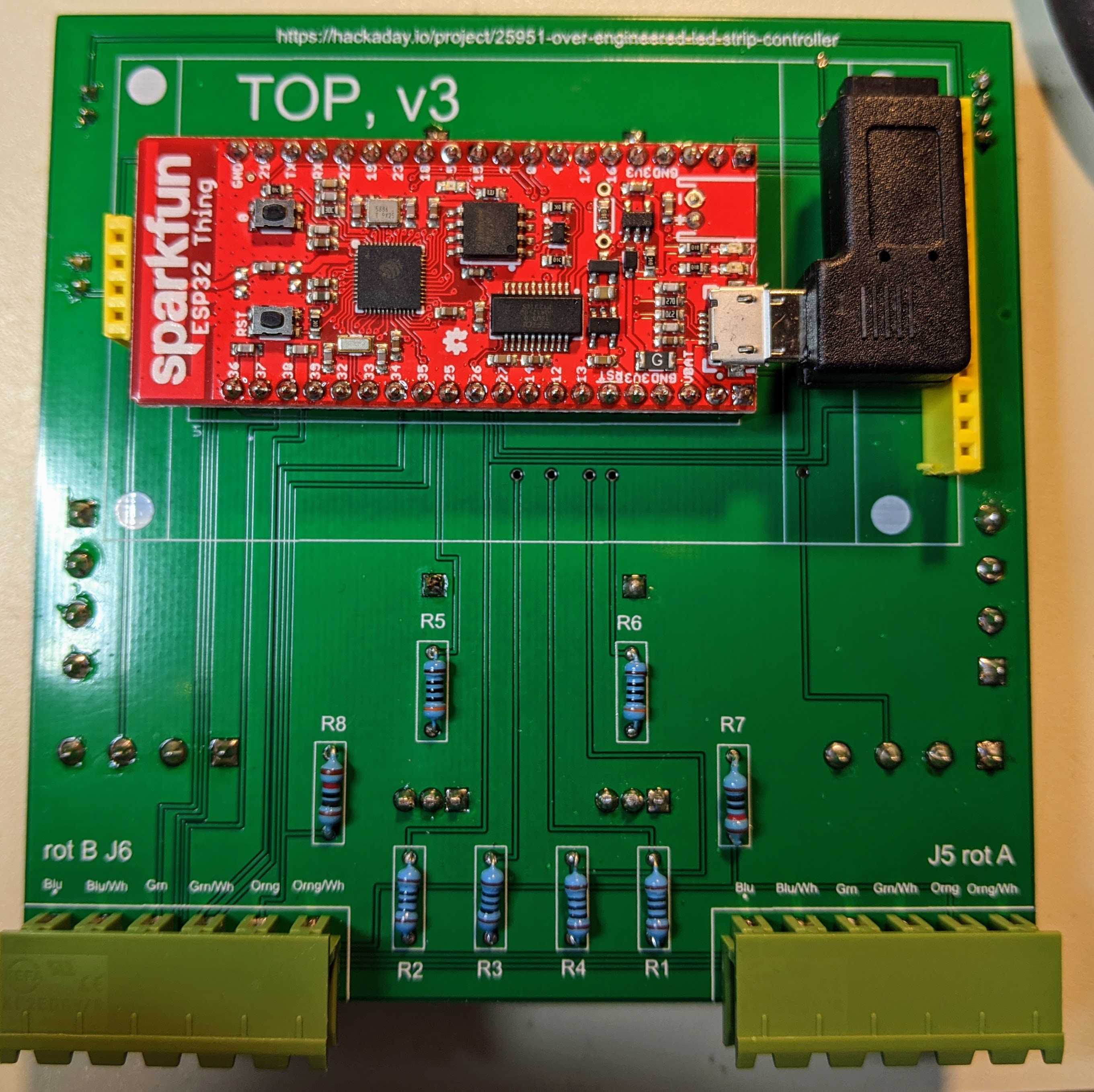
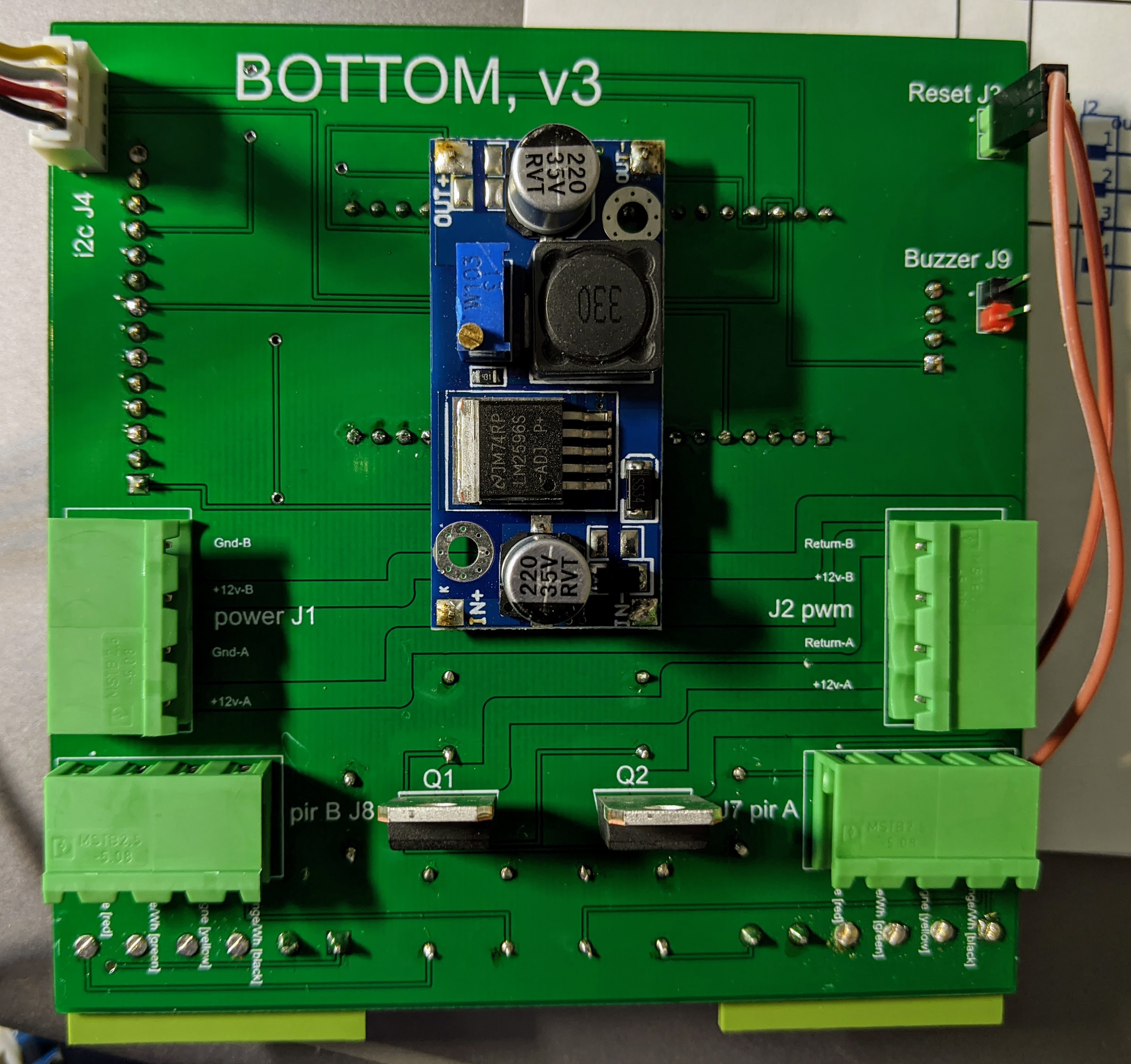
Here are pictures of the top and bottom of the main PCB after all parts have been attached.
![]()
Photo H. Top side of board The display board has been removed in Photo H to show the microprocessor board.
![]()
Photo J. Bottom side of board The wiring for the I2C bus and the reset switch are connected in Photo J.
 WJCarpenter

Discussions
Become a Hackaday.io Member
Create an account to leave a comment. Already have an account? Log In.