-
11Smoke test
![]()
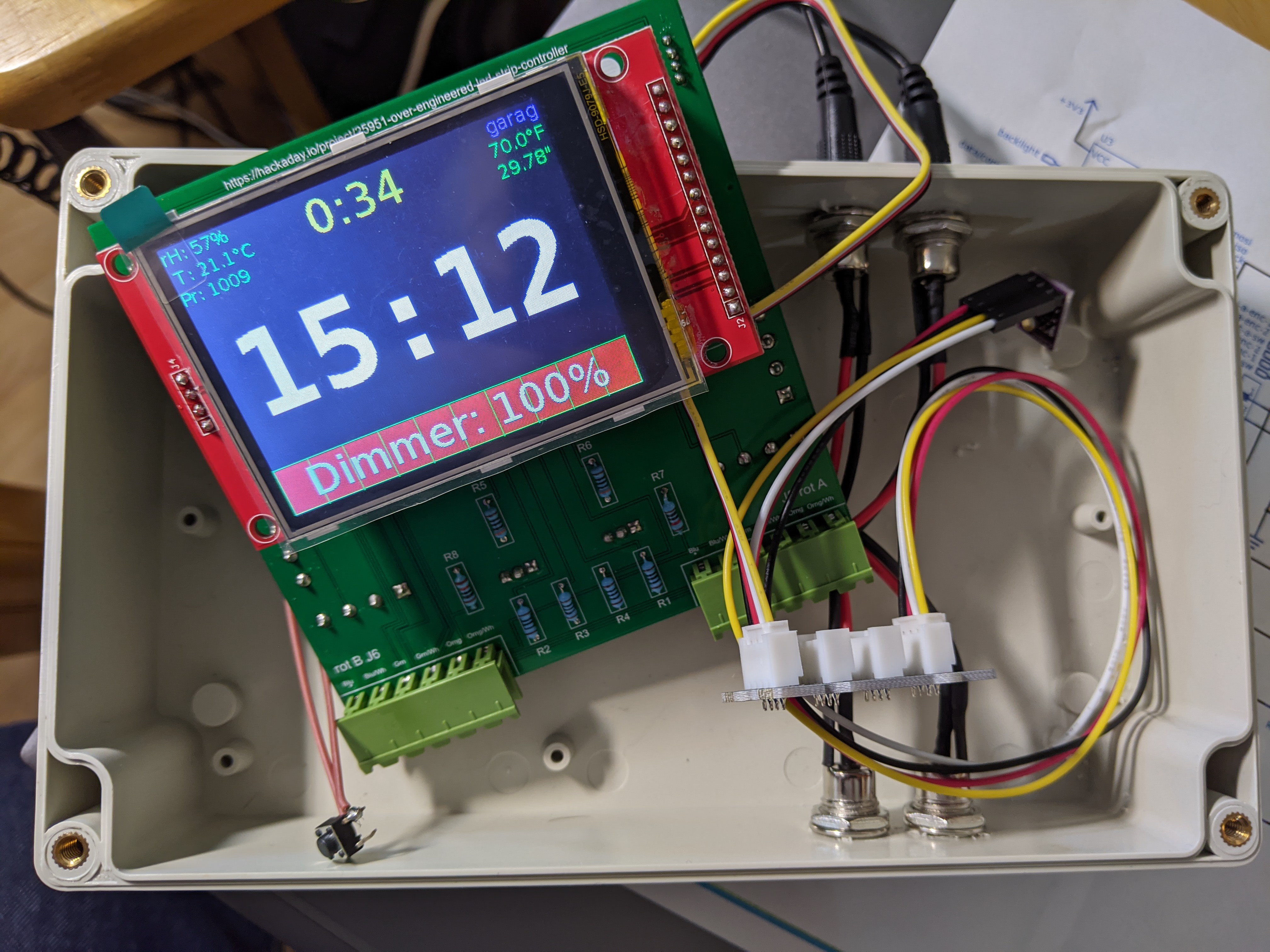
Photo K. No smoke so far! Assembly of the main PCB is now complete.
Locate the 4-pin terminal block on the bottom side of the PCB with the label "J1". (It's near the middle of the left side in Photo J in the previous step.) If you apply 12vdc to pins 1 ("+12vdc-A" on silkscreen) and 2 ("Gnd-A" on silkscreen), it should power up the microprocessor board and display (assuming you have uploaded some firmware that displays something). If that happens, it proves that the on-board power supply is working correctly, and there isn't anything too seriously wrong with the rest of the wiring.
Photo K was taken after I had already done some work on the box that will hold the circuit, so the power is fed through the connectors and the J1 terminal block on the bottom side of the board. The display reflects the software layer being pretty far along in the prototyping stage. The I2C bus is connected through a Grove I2C hub and then to a BME280 sensor. The upper right and left corners of the display show actual readings from that sensor.
 WJCarpenter
Discussions
Become a Hackaday.io Member
Create an account to leave a comment. Already have an account? Log In.