WJCarpenter
-
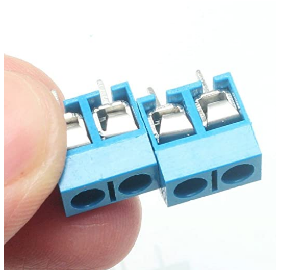
Clip-together terminal blocks
08/15/2020 at 20:46 • 0 commentsI came across these today (Amazon thought I might be interested!). If I had known how haphazard it would look to line up multiple 2-pin terminal blocks, and if I had known about these, I might have tried using them. They're the same sort of 2/3/4-pin screw terminal blocks, but they can be clipped together to make various combinations in a fairly straight line. It would not eliminate the problem I came across later (fiddly, broken wires from the Cat3 cable). So, I might still have changed to the Phoenix connectors. They look handy to keep in mind for some possible future project where that isn't an issue.
![]()
-
Revising my connectors
08/09/2020 at 01:07 • 0 commentsI finally gave up on the screw terminal blocks I was using originally. Aside from looking kind of sloppy due to play in the alignment, I found lots of delicate wires were coming undone or breaking off as I fiddled with the board. Even though I don't plan to disassemble this thing for maintenance very often, I expect to do quite a bit of trial and error as I get it placed into the mounting box.
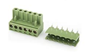
I decided to use these "Euroblock" connectors made by Phoenix Contact. (Actually, I think the ones that I have are made by someone else, but "Phoenix connector" is a common name for Euroblocks.) All in all, they are pretty expensive, but I'm only using a few of them. It's a bit hard to visualize how these actually work if you don't have one in front of you. In the picture below, you can see the tops of the screws on the plug on the left. On the hidden bottom side, there is an opening for inserting your wire. The things on the plug that look like chimneys are the parts that slide over the pins of the socket. Imagine the socket (on the right) flipped over and having those protruding pins through the PCB. Then the "chimneys" of the plug slide over the pins in the open channel of the socket. At that point, the screws will have their tops facing up.
![]()
When the plug is then inserted into the socket, it makes a very solid connection. The plugs can still be removed from the sockets with a little effort. The sockets are available with either straight or right-angle pins. I decided the right-angle type work best for me in this project. Using these Euroblock connectors also means forgetting about the 6P6C Keystone jacks mentioned in an earlier project log. The wiring will now go into the Euroblock plug instead.
The pins on the Euroblock sockets are pretty big since they are commonly used for something beefier. They just barely fit, with a little persuasion, into the holes in my PCB. I found that the residual solder left in place after I removed the original screw terminal blocks was too much for placing the Euroblock sockets. I just couldn't get them cleaned out enough. So, I started over with a clean, blank PCB.
Luckily, I had 10 in my original PCB batch. I have spares for most of the parts, so clean desoldering is only necessary to avoid waste. The one part that I didn't have as a spare is the Sparkfun ESP32 Thing. I mainly chose that specific board since I had it on hand for some reason. I tried desoldering it from both sides of the header pins, but I've done so much monkeying around that I ended up lifting a couple of pads. I gave up and ordered another one.
-
Wire colors for remote boxes
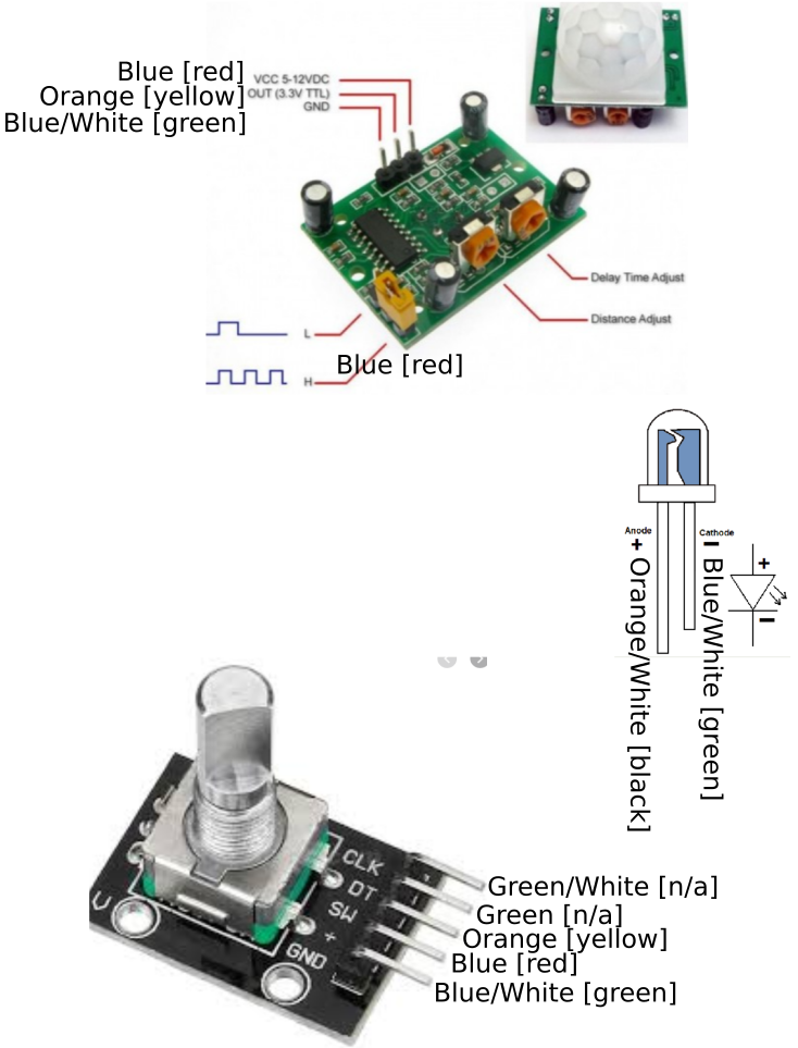
08/02/2020 at 20:06 • 0 commentsRemote from the main controller board are 2 rotary encoders with switches and 2 PIR motion sensors. Each remote box also has a separate LED for feedback/indications. With shared ground connections and shared 3v3 connections (where possible), that implies 6 wires for the rotary encoder remote boxes and 4 wires for the PIR remote boxes.
I'm using Cat3 cabling for the runs from the controller board to those remote boxes (including for the PIR remote boxes, where I only need 4 wires*). Cat3 cables is also known as 6P6C (6 pins, 6 conductors) and consists of 3 distinct pairs of wires. I'm using this kind of cable because (a) it's cheap and widely available, and (b) the standardized color coding of the wires is very helpful: blue, blue/white, green, green/white, orange, orange/white. The abbreviations for those colors is on the silkscreen for the PCB and simplifies hooking things up. To facilitate easy removal of the controller board, I used keystone jacks to wire up short lengths of Cat3 to the screw terminals. There will be matching RJ12 plugs on the cable ends nearest the controller board.
(*OK, a little white lie. When it came time to run the cable, I ran short of Cat3 by several feet. So, one of the PIR remotes uses standard 2-pair telephone wire, which uses a different color scheme: black (orange/white), red (blue), green (blue/white), yellow (orange). Luckily, I arbitrarily [I think] didn't use green or green/white on my PCB markings, so I can be slightly less confused when wiring this up.)
Here is a diagram of the pins of the components in the remote boxes with labels for the wire color coding. The color names in the [square brackets] are for the 2-pair telephone cable as an alternative to the Cat3 colors.
![]()
-
A hatful of mistakes
08/01/2020 at 21:21 • 0 commentsAlong the way, I've come across some design errors and other mistakes I've made. Some of them are more like lessons learned than actual mistakes. This is a consolidated list. Some have been or will be mentioned in more detailed project log entries. These would be inconsequential if this were an iterative design. I'd just fix them up and keep going. However, I expect that I will build exactly one of these garage door lighting controllers, so I'm working around them.
- [fixed in V2] In the PCB layout, I didn't allow enough space between the holes for the display screen mounts and the nearby screw terminal mounts. I worked around that by flattening the pins for the display screen mounts, and I turned one set of screw terminals around by 180 degrees. (Detailed in build instructions step 4. However, after switching to Phoenix connectors, turning by 180 degrees was no longer necessary.)
- [fixed in V2] Some GPIOs of an ESP32 do not have internal pull-up/pull-down resistors. I used two of those GPIOs where I needed pull-downs. I worked around that by adding the pull-downs across some existing pins. (Described in project log Pull up! Pull up! Pull up!)
- When testing those pull-down resistors after I soldered them, I was expecting to see about 10k ohms. Instead, it's pretty close to (but not quite) zero. There is no short between those holes in an unpopulated PCB. I'm still working on finding the cause of that problem. [I figured this out. Those resistors were just bad. They were from a batch I had on hand with a "10k" label, but they weren't anything near that. I swapped them for some 15k resistors that I measured before placing them.]
- OK, I'm an idiot on this one. Even though I called the project log item "Pull up! Pull up! Pull up!", I somehow ended up believing I needed pull-down resistors for the switches on the rotary encoders. I even had pull-ups working on the breadboard after I figured out the ESP32 GPIO situation. On the PCB, my switches seemed to be always either stuck "on" or "off", depending on my software configuration. When the light dawned on me, I rewired the resistors to pull up, and things worked as expected.
- [fixed in V2] I probably should have added I2C to the design in the first place, even if I didn't have a specific use for it, but I wasn't sure if I could use the RX/TX pins for I2C. When I tack-soldered wires for an I2C bus (described in project log Adding i2c), I arbitrarily planned to use GPIO22 for SCL. When the time came, I discovered that my "no connect" pin was somehow tied to ground. It's not grounded on an unpopulated board. Maybe I'll find it's related to the problem with the pull-down resistors (I hope, I hope [edit: nope, nope]). I changed my plan and instead used GPIO3 (right next to it) for SCL instead.
- It's a good thing that I am using a framework (esphome.io) that allows for OTA updates. It's easy to pop the display off the mounting headers to get at the Sparkfun ESP32 Thing, but there is not enough room for me to insert a cable into the micro-USB port. It's at least 1/8 inch too cramped. (I found this blunder pretty funny when I first noticed it.) If I were not using OTA, I guess I would do a more thorough search of my vast collection of micro-USB cables to see if I had one that fit. Or, maybe I would buy some kind of right-angle micro-USB thingy. Or, worst case, wire up some kind of custom USB monstrosity myself. [Update: I ordered a few right-angle micro-USB adapters. I don't have them yet since they are coming from somewhere in Asia, but it looks like they should easily fit. They are fairly inexpensive, so I'll probably plug it in even though I don't need it right now. If I ever do need it, I want to make sure I can find it.]
- [silkscreen text fixed in V2] I'm pretty happy with the manufactured PCB and most of my own work. One thing that I would do differently would be to increase the size of some of the text on the silkscreen layers. I would also increase the size of the lands around some of the holes. Both of these looked plenty big when looking at the layout on a screen, but I faked myself out due to my own inexperience in realizing how small they would be on the actual PCB. One might say I didn't have the right perspective (nyuk, nyuk!)
- [fixed in V2] I probably would use something other than the screw terminals for connecting the off-board wiring. They're OK, though the "play" in the plastic housings gives a less tidy look than I wanted. And, all that wiring does add a certain bulk overall. Perhaps in future projects, I'll use JST connectors or something similar. (See Revising my connectors. I eventually switched to a different kind of connector.)
- [fixed in V2] I got the wiring for the MOSFETs completely wrong (see Circuit to nowhere). It's a pretty serious mistake with potential for making some smoke. There's no excuse for it. It's just a blunder in transferring from breadboard thinking to schematic thinking.
- [fixed in V2] On the PCB layout, I was using an off-board connector with a 5.00 mm pitch instead of 5.08 mm. That might account for the snugness of fitting the euroblock connectors that I used.
- [fixed by pretending it wasn't a mistake] I used a wrong PCB footprint for the I2C bus connector. See Grove connectors. I was able to resolve that by pretending that I had intended to use Grove connectors all along.
-
Gestures
07/28/2020 at 02:13 • 0 commentsWell, OK, the problem of making the display visible is probably solved, but that brings with it another minor problem. My display has a touch interface, and I was vaguely planning to use that to trigger the display of some internal info or whatever for my own geeky needs. I was not planning to use that for reconfiguration or for actually controlling the lights, but I might be able to display some configuration info or logs or something.
I'm pretty sure the display I have uses resistive technology, in which case it definitely will not work through a plastic cover. Even if it turned out to be capacitive, the cover would probably have to be pretty thin for it to be usable. Oh, well.
I happen to have on hand a few APDS-9960 gesture sensor boards. They operate over I2C, and I already planned to have I2C for the BME280 environment sensor. I should probably be able to use one of those gesture sensors through the plastic cover for simple things like displaying extra "pages" of information.
I'll have to save additional details about that for when I get bogged down in software design.
-
A clear case
07/28/2020 at 02:05 • 0 commentsNow that the board is assembled, it's time to get serious about the case I am going to put this in for mounting on the wall. I've dithered about this before in earlier project logs. Yesterday, I made a trip to the local big box hardware store to see what I could find off-the-shelf.
Ever since I decided to add the display to the project, I've been thinking about how to make the display visible. Something I know from many past projects is that precisely cutting out a rectangular shape in anything, including soft plastic, will look a lot better in my mind's eye than it will when I actually try it in practice. In fact, I've been dreading that.
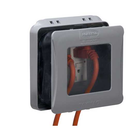
So, I've reverted back to the idea of a clear cover. Finding a clear cover for a 2-gang electrical box is not that easy, especially if you want it to be completely blank (ie, no cut-outs for switches or sockets). But it dawned on me that there are outlet covers that are more or less clear. For example, this item from Hubbell TayMac.
![]()
That's a little bulky (and pricey), but maybe it would do. I decided to just think about it. When I got home and looked at more information on the manufacturer's web site, it seemed like it wouldn't have the depth I need except by expanding the cover. If you do that, it becomes a lot less rigid. That's not a problem for its intended use, but it's less ideal for my use.
I also spent a bunch of time looking at different 2-gang electrical boxes and their friends. Some seemed like they might be suitable if I could just solve the problem of the cover. But another thing I've learned through hard experience is that I always need a lot more room than my mental picture of how the wiring will go. I started to worry about how cramped it would be. This PVC box from Legand Wiremold is 2-gang, but it has more elbow room than a typical in-wall electrical box. It's shallower, but it's deep enough for my use.
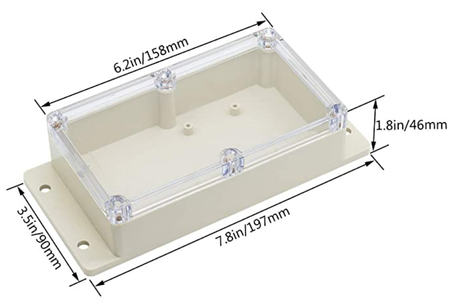
When I got home from my mega-hardware-shopping trip, I decided to have another go at finding a clear blank cover plate. With some luck in the Google-fu, I found some ABS plastic boxes with clear covers. The brand is Lemotech. I found lots of places selling them online, but I didn't find a web site for the manufacturer. I ordered this one from a well-known e-commerce merchant.
![]()
They come in lots of different sizes. The one in the picture is about US$10. I could have used a smaller one, but I rethought the physical arrangement of this project in my garage. I was originally going to have a central control unit that would house the board and the display, and then there would be two remotely mounted rotary encoder switches for turning the lights on and off and controlling the dimmers. I'm now thinking that. One of those rotary encoder switches will be mounted on the end of this box with the controller. There's plenty of room for the zillion wires I will have to connect to the board, and I don't really need very much interior room for the rotary encoder.
I don't have this box in my hands yet, but I have high hopes for it. Finally, the problem of making the display visible is solved.
-
Put the metal to the metal
07/26/2020 at 00:31 • 0 commentsToday was finally the day. I assembled the main board. After all of that, I hooked up a 12vdc power supply to the "a" power input, and the screen came alive with my test outputs. I found a couple of glitches during assembly, and I've done enough projects to know there could be more waiting for me as I start wiring up peripherals, but it felt pretty good seeing features instead of smoke.
Here's a picture of the assembled board (except for the display, which slides into those blue sockets on the ends; some barbarian let the soldering iron touch the shorter one).
More details in the build instructions.![]()
-
Adding i2c
07/25/2020 at 01:19 • 0 commentsI've pretty much decided to add an i2c bus using a couple of unused pins on the processor. I have a few bme280 temperature/pressure/humidity sensors laying around from another project, and it will be interesting enough to get that environmental info from my garage.
On the PCB, I isolated the lands for those no-connect pins. I should be able to easily tack-solder onto the pins of the processor board for the signals. For Vcc and Ground, I have plenty of places to tack-solder. For one of the pins, I have to use a pin that is set aside for UART Rx or Tx. I wasn't sure whether those would work for i2c, but since I am doing OTA updates, I think they are available without any problems. I did a test on the breadboard, and it works fine.
This won't be as tidy as bringing it out to a screw-terminal connector, as I did with all of the other off-board connections, but I can live with that. To keep the sensor away from being influenced by the main board heat, I'll have the sensor dangling with a few inches of ribbon cable anyhow.
Hey, still 2 GPIO pins left on the microprocessor board (one of which is the on-board LED). Come on, think! There must be something I can cobble together with that.
-
The current breadboard
07/24/2020 at 20:18 • 0 comments{Editor's note: I re-read all of the project logs to refresh my memory of some things. I was surprised to find out I had started the project log almost exactly 3 years ago. That's slow, even for me, and I was already thinking about it for a while before I got around to making this hackaday.io project. Sheesh.]
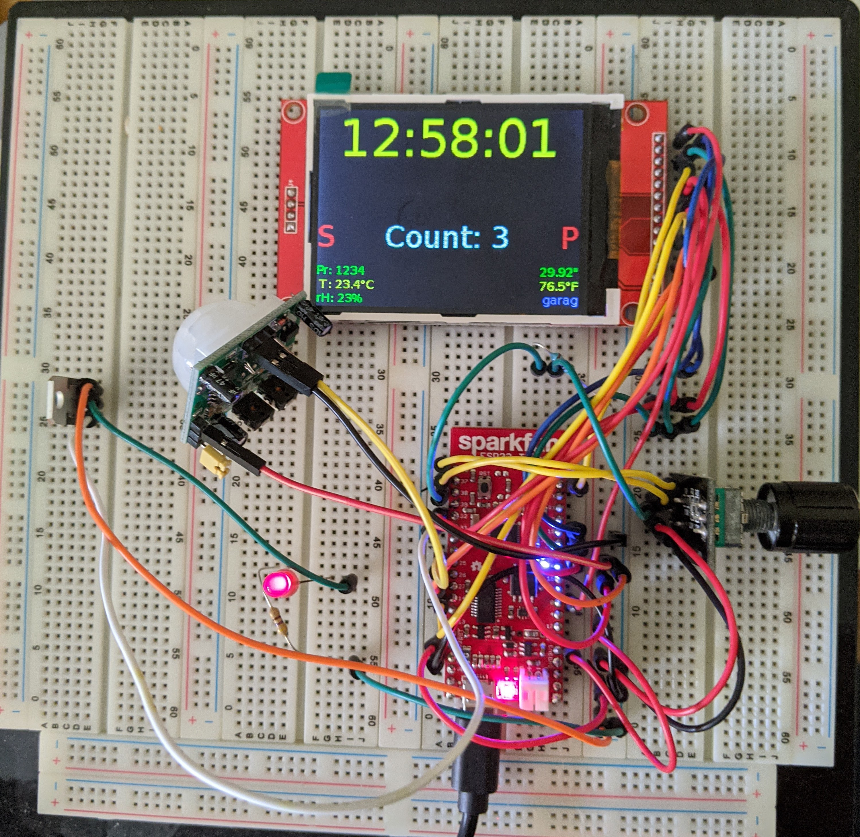
I've got most of the logic of the circuitry laid out on a breadboard now. Since this is just proof-of-concept for the esphome.io stuff, I only bothered with a single PIR sensor and a single rotary encoder. For the dimmer feature, I am driving an LED through one of the N-channel MOSFETs that I plan to use. The display is just showing some simple status information as I test things out. I haven't yet designed what the display will look like when the system is operational.
![]()
- The "S" changes from red to green while the rotary encoder switch is pressed.
- The "P" changes from red to green while the PIR data line is high.
- The "Count" value is keeping track of rotary encoder ticks.
- The clock value is kept in sync OTA by a esphome.io component. (Who doesn't need another clock?)
- The smaller text is just dummy stuff so I could get an idea of the font rendering.
-
Looking at esphome.io
07/22/2020 at 03:48 • 0 commentsWhile I haven't been actively working on this for a while, I have been thinking about the software design from time to time.
I've always imagined a paradigm of having a thread react to inputs from the PIRs, the rotary encoders, and the switches on the rotary encoders but putting things onto some kind of queue. Another thread would manage state and process items on the queue. That seems grand, indeed, though it might mean getting pretty far along in the Espressif SDK native features.
It so happens that for another little project I decided to finally take a look at esphome.io. That project makes it pretty easy to do simple sensor readings and have them feed into MQTT and/or https://www.home-assistant.io/. I wondered if it were worth the trouble, and I was overwhelmingly pleasantly surprised. It's well-documented, easy to work with, has good tooling, and it already supports zillions of things you might hook to your esp8266 or esp32 board. For things it doesn't directly support, it's often simple to add them as custom components, and for a lot of natively-supported things you can escape into Arduino-esque C++ to get exactly what you want. There's a vibrant community of people doing things with it, so it's not just "some guy" that you're depending on to have all of the ideas. The bonus is that your can do over-the-air (OTA) updates to the firmware after the first USB-connected upload. Pretty cool.
OK, that's great for scattering bme280s around your house, but can it be used for something as *cough* sophisticated as this project? I believe it can. It still has that simple-minded Arduino loop() inside, but it packs a lot into it while still iterating that loop pretty fast. I was afraid the busy loop could miss input events, but so far it seems to be fast enough.
My plan is to let esphome handle the low-level dealings with the inputs and outputs. I'll use the equivalent of a state table to react to the processed inputs and tell esphome what to do with the outputs. I'm back to breadboarding things to prove in individual components one at a time to make sure they actually behave in the way I expect. So far, so good.
Over-engineered LED strip controller
Way too much stuff to light my garage MY way.