My idea that I could simply connect all buttons of all controllers with vcc or gnd and a digital pin came out to be wrong as I recogniced that the pins of my USB Boarduino v2.0 were not enough. My first solution was to use the Fubarino I won at the hackaday Fubarino Contest, but the NeoPixel library by Adafruit didn't worked with the PIC processor. So I needed to came up with another solution.

Each button on the controller will be connected with the reply pin and one of the other pins. The system works that way:
- shift out on the 74HC595: Q0 low and the rest high
- readout the reply pins ( low = button1 of that controller is pressed / high = it isn't )
- shift out on the 74HC595: Q1 low and the rest high
- readout the reply pins ( low = button2 of that controller is pressed / high = it isn't )
- ...
The 9th pin is conected with a digital pin of the arduino, because I thought it would be a bit dissipative to use a second 74HC595 just for one pin.
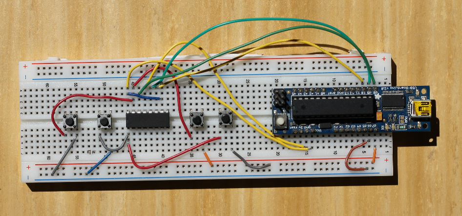
First I made some test on a breadboard, because I didn't knew 100%ly that it would work.

It worked with a limitation: More than one button at the same time didn't worked. Maybe its possible to solve with some diodes on the controller. ( If someone knows a solution for this, I would be glad to hear from you )
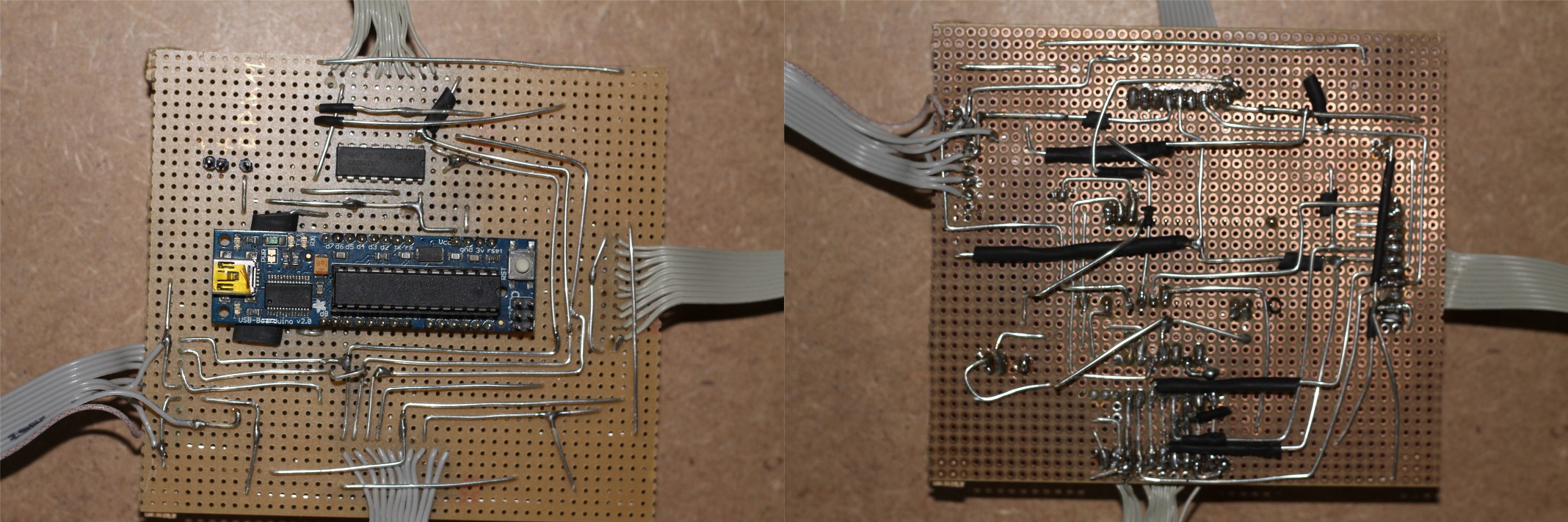
This is the final <irony> professional, cleanly designed board. Using sisams "3D adhoc wiring technologie" (tm) </irony>.
 sisam
sisam
Discussions
Become a Hackaday.io Member
Create an account to leave a comment. Already have an account? Log In.