 Phil Handley
-
RF Heatmapping for Radiolocation?
07/23/2017 at 23:46 • 3 commentsUsing a drone to hunt radio beacons opens up some radiolocation techniques which aren't necessarily available to a human tracker on foot. With the drone's ability to quickly and easily fly grid search patterns over any terrain, one possible radiolocation technique I'm keen to try out is generating an RF heatmap.
![]() RF heatmap showing WiFI signal strength in a building.
RF heatmap showing WiFI signal strength in a building.RF heatmaps aren't a new thing, but they mostly seem to be used as a way of showing the signal strength of WiFi in a building, or cell network coverage. They're a way of visualising the strength of radio signals over a geographical area, with a colour scale to represent the strength of the signal at that point on the map.
My plan is to fly a grid pattern over a given search area, and use an omnidirectional antenna mounted to the drone to take periodic measurements of the signal strength of the beacon. By pairing the measurements with the GPS coordinates of the drone, this should produce a map with a big red area showing the location of the transmitter. By using the stepped attenuator discussed previously to reduce the signal strength when close to the beacon, I'm hoping this technique should be able to provide a very accurate location for the becon.
This should act as a complimentary radiolocation technique to the radio direction finding (RDF) techniques discussed in a previous log. The RDF techniques are best used when initially looking for the beacon - they should be able to determine a reasonably small area (few hundred square meters) in which the transmitter is located. When the drone has reached this area, the RDF may become overwhelmed by the signal strength and not be of much further use. In this case, the drone can switch to the omnidirectional antenna and begin flying the grid pattern to produce a heatmap.
To see if this concept works as expected, I'm first going to knock together a system on my latop to test it out on foot. I plan to use a NavSpark Mini GPS reciever (and microcontroller), since there's already one plugged into my computer for another project, and an RTL SDR dongle. A small C program will periodically call rtl_power to take signal strength readings from the SDR, and retrieve the current location from the NavSpark, storing to a CSV file. I've had a look at the available heatmap generating libraries and none of them seem to do what I want, so I may well also have to write a quick script to generate a KML file containing the heatmap for use in Google Earth/Maps.
Development of this test setup should take place in the next day or two, so stay tuned!
-
Stage 3: Build a Rover!
07/23/2017 at 23:01 • 0 commentsBecause multirotor drones are terrifying, flighty, barely-controlled robots with spinning-blades-of-death on every corner, I decided that it would be a good idea to use something ground-based to test the more autonomous aspects of the project before they go on the drone.
One of the fantastic things about the Ardupilot autopilot project is that, being a well-supported open source project, lots of variants of it exist using the same main codebase. In addition to supporting multirotors and fixed-wing aircraft, there is also a variant called Rover designed for autonomous ground vehicle platforms with great support for typical R/C car hardware. Building a rover not only allows me to test RDF techniques and hardware on a remote vehicle, it also lets me build experience and code for autonomous operations using the Ardupilot platform at the same time.
![]()
My requirements for the R/C vehicle used here were pretty minimal - it had to be big enough to carry the APM2.6 + accessories, the Raspberry Pi + SDR and various antennas, and ideally be happy driving on grassy fields. A quick search on eBay brought up a pretty ancient Traxxas Stampede R/C truck for a steal and was quickly purchased. It arrived with a nicad battery, 27MHz R/C system, brushed DC motor and mechanical speed controller. These were quickly (and very cheaply - how did people afford this before Hobbyking?) replaced with the biggest 2s LiPo battery which would fit, an electronic brushed speed controller, and an FrSky 2.4GHz R/C reciever.
After that nothing happened for quite a few weeks as it was actually quite a decent R/C truck, the sort I'd always wanted as a kid, and I was too busy playing with it to turn it into a rover!
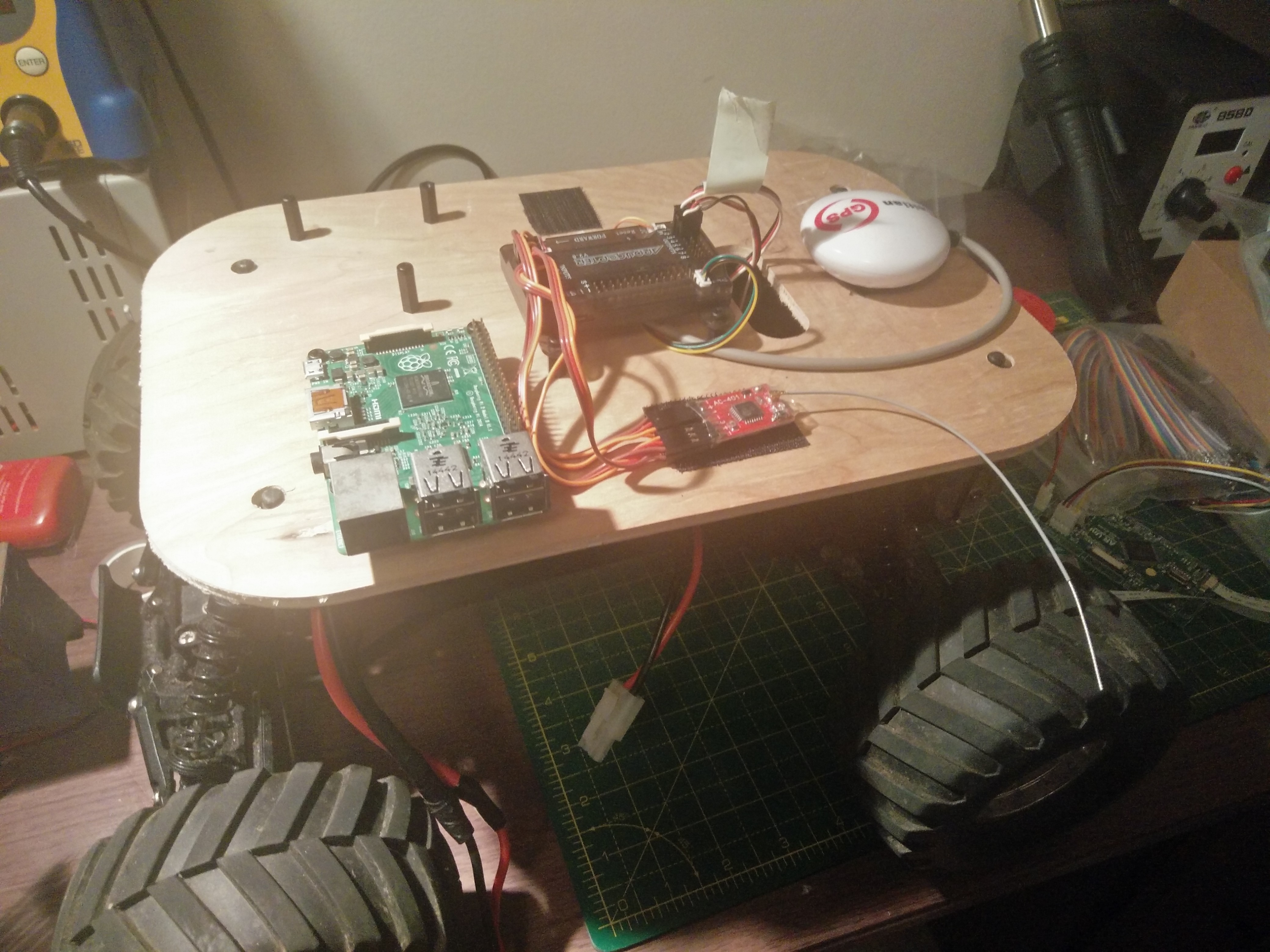
Eventually, I designed a mounting plate for the APM, GPS/etc and Raspberry Pi/SDR. This was cut out of 6mm plywood on a CNC mill, and fits on the body shell mounts of the truck. Antennas under test will be mounted on a wooden pole somewhere towards the front, probably with cable ties.
![]()
So far it drives well with the R/C passthrough enabled on the APM. Unfortuntately I haven't had the time to take it out to an empty car park or field and play around with the autonomous functions of the APM yet, but am hoping to soon.
-
Radio Direction Finding Techniques
07/23/2017 at 15:36 • 1 commentTo be able to locate a radio beacon using the drone, the appropriate radiolocation technique needs to be determined. This log entry looks at the methods available and assesses their suitability for using with SDR on the drone, to find the best method to begin playing about with.
Radiolocation Methods
There are two broad methods for locating the source of a radio transmission. The first, Trilateration, uses multiple geographically-separated omnidirectional receiving stations while the second, Triangulation, uses one or more directional receiving stations.
Trilateration
![]()
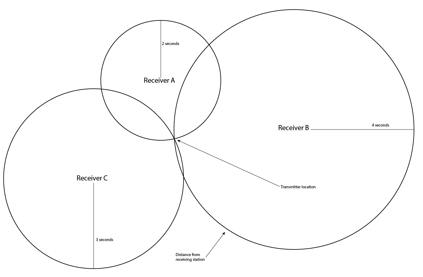
The first method uses a technique called trilateration [wikipedia]. Each receiving station measures the length of time taken for the radio signal to reach their position, and when the times from three or more receiving stations are known, a position for the receiver can be calculated. The advantage of this method is that each receiving station is equipped with a simple, omnidirectional antenna (the received signal strength is the same from all directions), however you need multiple fixed receiving stations, and each station must be equipped with a very precise clock in order to have any accuracy (since we're timing things travelling at the speed of light here).Unfortunately, we only have a single drone, so this method is not much help (however the theory does come in handy a bit later). If you're interested in a trilateration radiolocation project, check out the MoSAReX project.
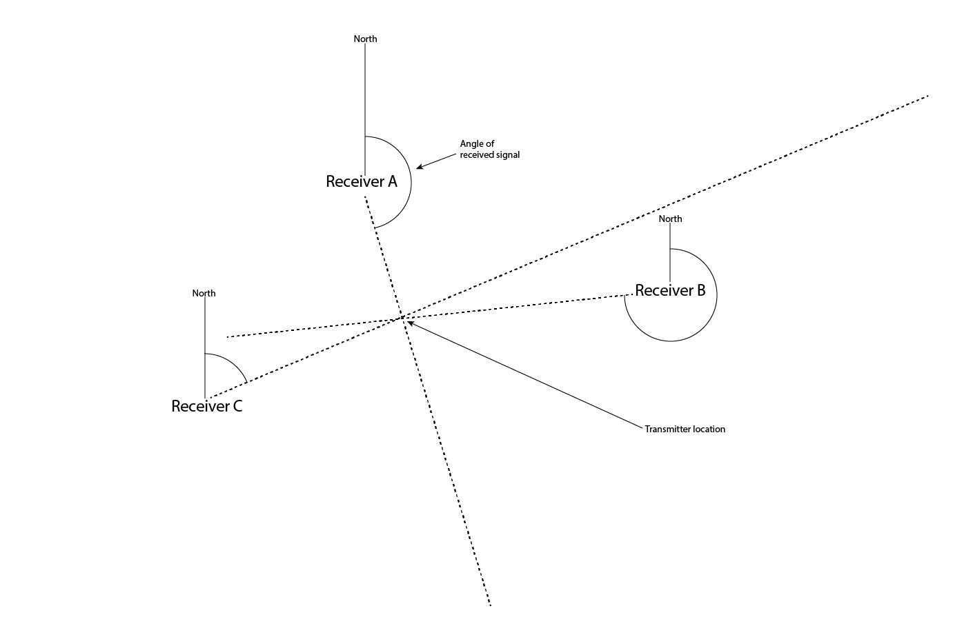
Triangulation![]()
The second method uses the slightly more familiar-sounding triangulation [wikipedia]. It can be used with multiple fixed-position receiving stations, as with trilateration, or it can be used with a single mobile receiving station. The station is equipped with a directional antenna (the received signal strength is much higher when the antenna is pointed toward the transmitter), and determines the angle which the signal is received from. When this angle is taken from three or more different locations, the location of the transmitter can be calculated.
The advantage of this method is that a single receiving station can be placed at each location in turn, and take a bearing to the signal. No clocks are involved, you just need to measure your position and the angle to the signal from a reference point (ie magnetic north) with reasonable accuracy.
When using triangulation manually in real life, the operator would typically select 3+ good sites on a map (ideally at on top of some nearby hills), go to each location, take a bearing, and plot the lines on a map. As shown in the diagram above, the transmitter should be where the lines meet. This is the process I plan to implement with the drone, with the added advantage that we can select arbitrary points in space (as long as they're above ground) to take the bearings from!
Radio Direction Finding (RDF)
To get a bearing on a signal, you need a way to find the direction the signal was transmitted from - this is the field of Radio Direction Finding [wikipedia], which has had lots of development thanks to its use in aircraft navigation for most of the 20th century. Rather than looking at professional aerial navigation systems however, at this point we'll be going off into the world of amateur radio and the sport of "Foxhunting" [wikipedia]. Not surprisingly, radio nerds have made a sport out of searching for hidden radio transmitters and dedicate quite a bit of effort to the equipment they use to help them.
Again, there are two main methods of RDF used in the foxhunting world - using a directional antenna (a "directive gain antenna" to be more precise), or using a direction-finding (DF) system.
Directive Gain Antennas![]() Radiation pattern of a typical Yagi antenna (ignore the Russian!) [wikipedia]
Radiation pattern of a typical Yagi antenna (ignore the Russian!) [wikipedia]As the name suggests, directive gain antennas achieve their directionality by applying gain (increasing the recieved signal strength) in the direction the antenna is pointing. Think of this in the same way you can focus the light from a lightbulb by using a reflector - it's the same amount of light, but concentrated in a direction rather than going out in all directions.
The most common example of this sort of antenna is a Yagi antenna, which looks like your standard long-and-pointy TV antenna. These are simple, really easy to make, and can have reasonable direcionality (10-20 degrees beamwidth). Unfortunately they're quite large and ungainly, which could present problems mounting it to the drone, although that can probably be worked around.
The fact that these antennas have a high gain is both good and bad - if the signal is weak, or far away, having a high gain directional antenna is a real advantage. However, as you get closer to the signal and it gets stronger, having a high gain antenna can be a pain if it is your only method of determining direction - it can become less sensitive to direction. Using a stepped attenuator (see later) can help overcome this somewhat.
A directional Yagi antenna seems like a good plan B for the drone. It has quite a few downsides for typical expected use cases - it's bulky, has quite a wide beamwidth, and taking a bearing requires the drone to hover and rotate a full 360 degrees. The high gain makes it harder to use when close to the transmitter, however it could also be really useful in situations involving a transmitter which is weak or far away. So for now I'll focus elsewhere, but eventually it might be useful to integrate a yagi as a third antenna.
Direction Finding (DF) Systems
DF systems use multiple antennas to determine the direction of the signal. These come in two types, "homing" DF units which tell you which way (left or right) you need to rotate the antenna to be pointing directly at the transmitter, and doppler DF units which constantly tell you which direction the signal is in, regardless of which direction the receiver is pointing.
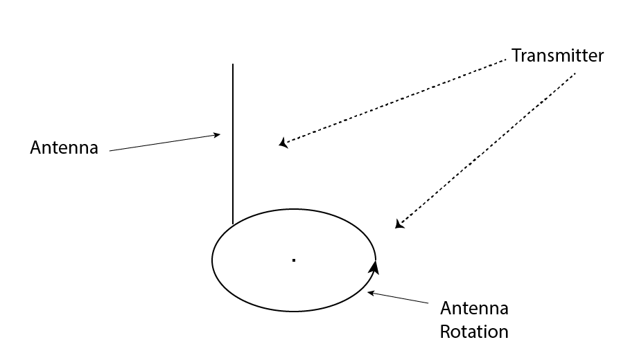
Doppler DF units work using the Doppler Effect - the same effect which causes a car horn to change pitch as it approaches you. A "true" Doppler DF antenna consists of a single antenna, rotating around a point in space at a high rate. As the antenna moves towards the transmiter, the frequency of the radio signal increases, as the antenna moves away from the transmitter the frequency decreases, and as the antenna moves perpendicular to the transmitter the frequency is the actual frequency of the transmission. So by observing the frequency changes of the received signal as the antenna rotates, you can determine the direction of the transmitter.
![]()
Making a rotating antenna like that is pretty hard, but luckily you can approximate the effect by making a circle of 4 or more static antennas and electronically switching between them at a high rate. This signal is then fed into a special receiver which analyses the frequency shifts and, traditionally, outputs to a ring of LEDs to show the direction the signal was recieved from. This sounds pretty perfect for my use on a drone, but has some drawbacks - implementation with an SDR, whilst possible (check out this great project from Balint making one with a USRP SDR) is a bit tricky in that the switching frequency of the antennas needs to be synchronised with the SDR's internal clock. This is pretty simple on expensive SDRs like the USRP (as it has a GPIO pin to generate the switching clock), but I haven't looked in to how easy this is to do with the RTL dongle.
Eventually I would like to try building one of these, just to say I've done it if nothing else. But the development work required is a bit much for a proof-of-concept build of the drone system, so this is on the backburner at the moment.
Of the various homing DF designs, one stands out as being highly directional, lightweight and, crucially, easy to implement in an SDR - the "TDOA" DF antenna. This DF system consists of two dipole antenas, mounted a quarter-wavelength apart. A circuit switches between the two antennas at a high rate, and is fed into an FM radio reciever. If the switching frequency is in the audible range, the radio reciever outputs a tone at that frequency. When the two antennas are in-line with the transmitter, the tone is at its loudest, and when the two antennas are perpendicular to the transmitter the tone is a its quietest, or is not there at all. Check out this HaD post describing one. Note: Time Difference of Arrival (TDOA) is a slightly erroneous name for this type of reciever, but seems to be the most common name in use so I will too.
This has several advantages for drone use - it only uses two antennas and should be very easy to process with an SDR. Additional processing with the SDR should also allow the antenna to determine whether the signal is to the left or right of the current direction, which would be really useful - making this DF system useful both for a "stop and turn" bearing, as well as simply flying towards the signal, turning left or right as indicated. One downside is that this antenna has a 180 degree ambiguity - when the tone is at its quietest, you don't know if the transmitter is directly in front of you or directly behind you. Taking multiple bearings and triangulating can solve this, and I'm hoping that doing additional processing with the SDR will let me determine this programmatically.
Due to the simplicity of development, I'm going to try using this sytem for the first proof-of-concept version of the drone.
Other RF Bits
RF Switching
As can be seen in the block diagram, an RF switch is required to select the antenna/DF system currently going into the SDR. These need to be able to be controlled by the onboard Raspberry Pi, so mechanically operated switches are off the table. Proper coaxial RF relays exist, but theyr'e crazy expensive and pretty heavy. At the small power levels that are being recieved, PIN diode switching circuits seem to be a good direction to look. Although they are a relatively complex option, they offer high switching rates and low RF loss when switched and are comparatively cheap - Digikey has a pretty good article going over the basics.Stepped Attenuator
Once a reliable switching circuit has been found, it also needs to be integrated into a stepped attenuator. This allows the incoming RF signal to be attenuated by a controllable amount (need to research how much attenuation is useful and in what steps), so as the drone gets closer to the signal the Raspberry Pi can use the stepped attenuator to make sure the signal does not get so strong it oversaturates the SDR.
Conclusions/TODO
- A "TDOA" reciever needs to be built and tested on foot to see if the directionality is fine enough and generally how well it works.
- TDOA reciever then needs to be integrated with RTL SDR.
- Research and testing needs to be done with PIN diode switch circuits.
- Research and/or experimentation needs to be done to see what levels of attenuation will be requied for the stepped attenuator.
-
Stage 1: Build a drone!
07/22/2017 at 23:35 • 0 commentsSo Stage 1 of the project is to build a drone - kind of hard to create a beacon-hunting drone system if you don't have a drone to test it with.
I'll admit right away, this stage of the project has taken waaayy longer than I originally thought it would. Building drones from scratch can be quite a learning process, especially if you've never even flown one before!
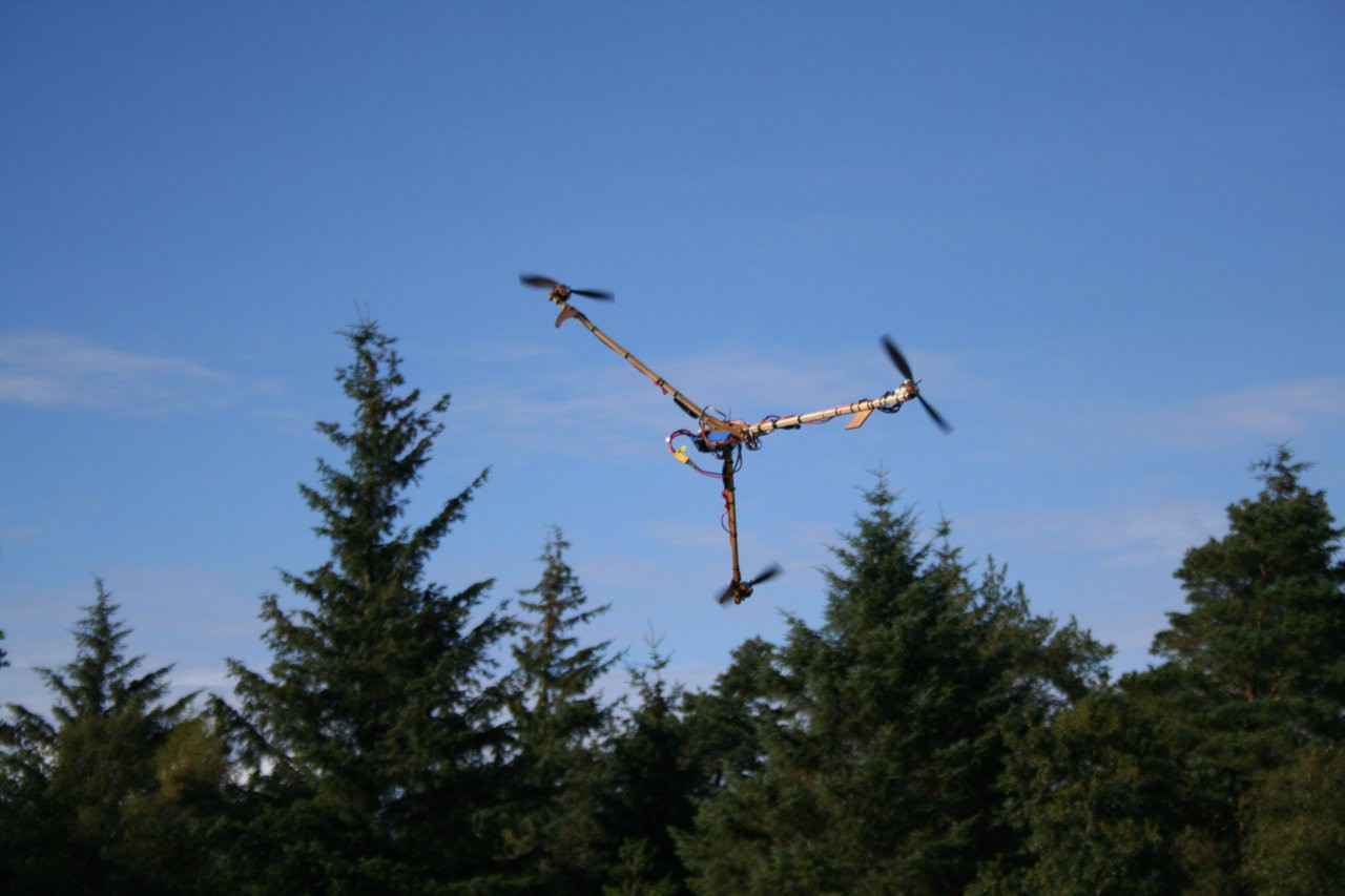
Starting with a multirotor rather than a fixed-wing seemed to be the obvious choice for developing the RF payload - the ability to hover at a given point in space and have precise control over the direction the drone is pointing in should come in handy during the latter stages of development. Instead of a more traditional quadcopter, I decided to go for a tricopter (three motors/propellers). Firstly I think they just look really cool, but the wide spread of the arms should give lots of room for mounting antennas and the servo on the rear motor provides really good yaw control, for pointing all those lovely antennas. Also, budget being a concern, three sets of propellers/motors/ESCs costs less than four sets, right?
![]()
I used the RCExplorer.se Tricopter v2.5 design as a starting point - I really like the build method and the way it's designed to crash cheaply (vital when learning to fly!), using cable ties to create weak points instead of damaging more expensive components. The way the front arms fold back for transport/storage is also really useful. Using the DXF files RCExplorer has published, I laser cut the frame and legs from 3mm plywood and used hardwood square dowel for the arms.
Originally I built it exactly as per the build instructions, including the KK2 flight control board. After trying to actually use the board, I quickly crashed the tricopter and chucked the KK board away. This was replaced with a Flip32 running Cleanflight, which worked a lot better and let me learn to fly, but still wasn't great.
(As a side note, I wouldn't recommend building your own drone as a first drone if you don't already know how to fly. When you're first learning with a home-built drone it gets very difficult to know if wobbles and instabilities are caused by your build being bad, by the PID tuning not being correct, or if you're just a terrible pilot. Or all three at once.)
After I was able to pilot the thing without crashing, I swapped flight controllers again and replaced the Flip32 with an Ardupilot APM2.6 autopilot. While the previous two controllers had no autonomous capabilities (just enough to stabilize it), the APM has GPS and enables the full range of autonomous autopilot functions. Switching to the APM, even with stock PIDs, showed a night-and-day difference from the Flip32. The flight stability was much better, and the position hold/return-to-home functions just worked straight out of the box.
The APM2.6 was great and did almost everything I needed. Apart from one thing - there was only one MAVLink serial interface to the autopilot, and this was used in flight by the telemetry radio, which is used to receive telemetry on a laptop and provide commands such as "Go to this waypoint" on the fly. But in order for the Raspberry Pi companion computer used in the radiolocation payload to control the autopilot, a MAVLink interface is required. After spending a while messing about with an ST Nucleo mbed dev board to act as a sort of MAVLink multiplexter/injector between the APM, Raspberry Pi and telemetry radio, I noticed the price of Chinese Pixhawk flight controller clones had dropped quite a bit, so I upgraded flight controller yet again. The Pixhawk runs the same Arducopter firmware as the APM2.6, but has three MAVlink serial ports on it, among many other improvements.
I won't go into too many details about the Tricopter build, as it's the RCExplorer Tricopter with a pretty standard Arducopter setup mounted to it. One thing that did require deviation from the RCExplorer design is the design of the top frame - I extended this and added mounting holes for the APM and all the peripherals (GPS, etc) it required. A DWG file can be found here.
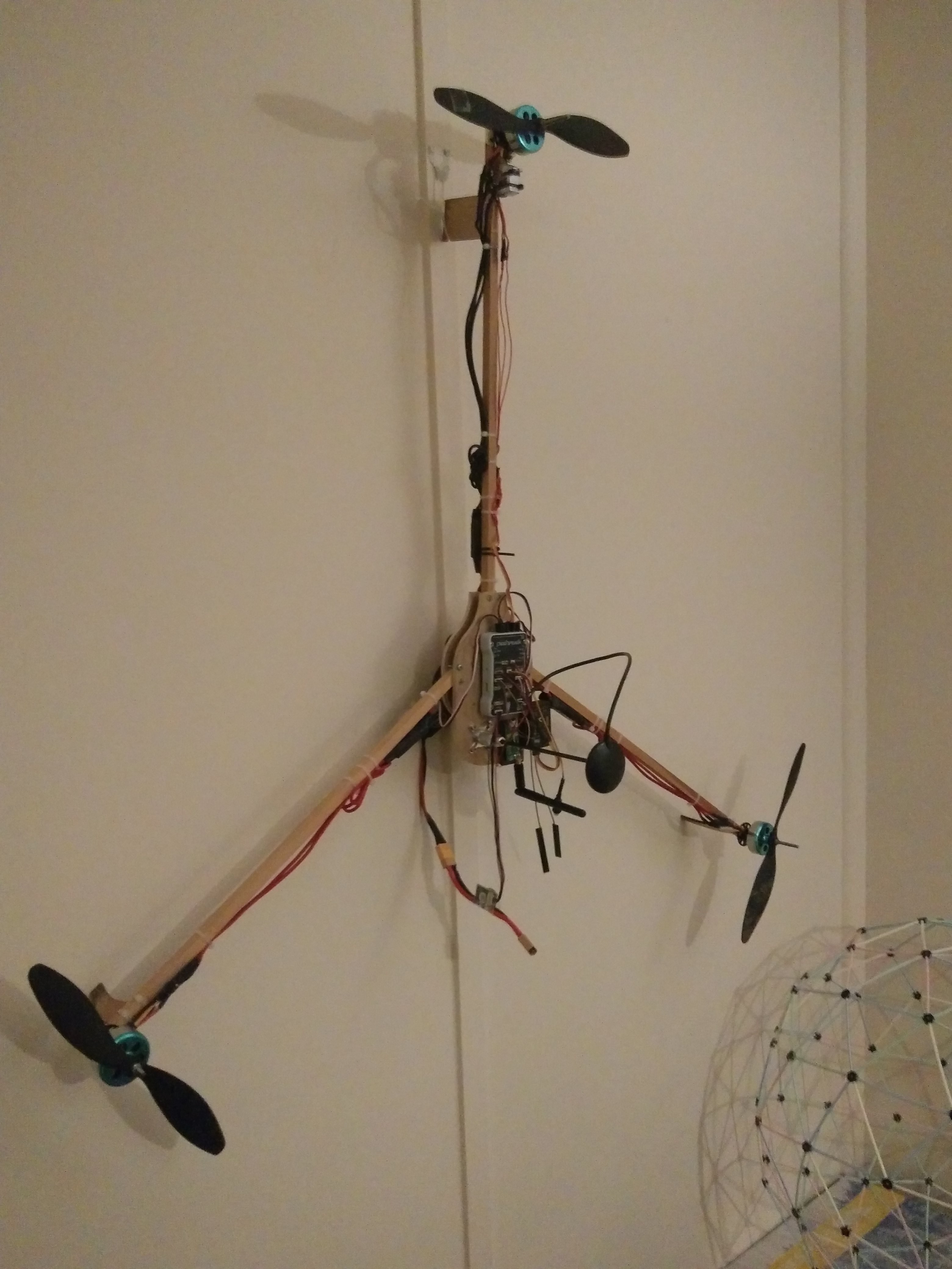
![]() Tricopter in it's current state with the Pixhawk flight controller.
Tricopter in it's current state with the Pixhawk flight controller.The flight time is around 15 minutes, which is a bit shorter than I would like. I'm hoping to try it with extra battery weight and larger propellers fairly soon, hopefully this should increase the flight time a bit. However, the flight handling and autonomous capabilities are finally at the stage where it's ready to have additional payloads mounted to it, without me worrying too much about expensive crashes.
Bloodhound: Autonomous Radiolocation Drone
Speeding up Search & Rescue by locating the position of emergency radio beacons using an autonomous drone.
 RF heatmap showing WiFI signal strength in a building.
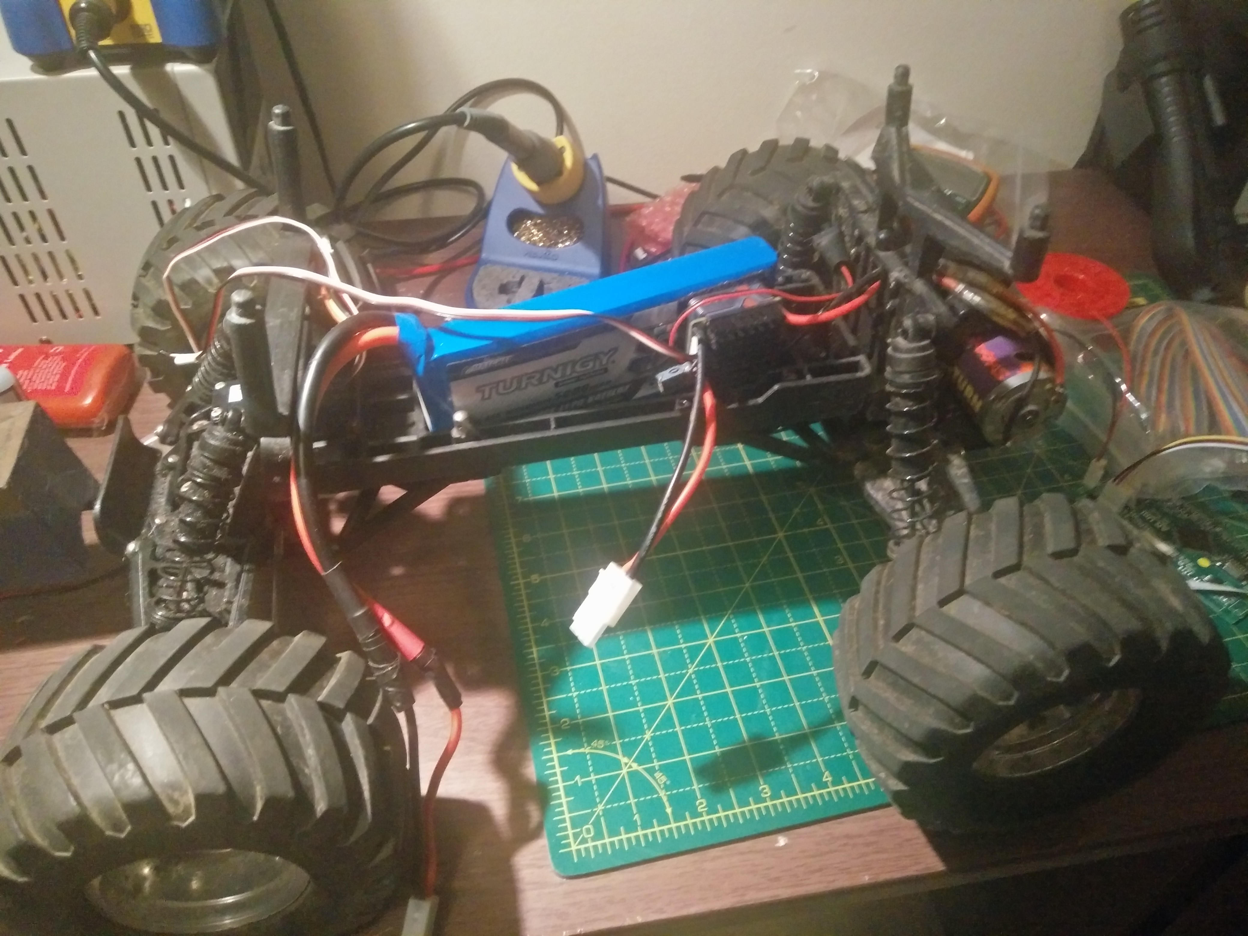

 Tricopter in it's current state with the Pixhawk flight controller.