-
Found a nice name for the poor thing: Tibi
07/24/2017 at 15:50 • 0 commentsAfter dealing with the red water replacement bottle, finally found a nice name for the robot: TiBi.
Tibi stands for TB (Tripping Balls) robot.
:o) -
Going Forward for a PoC (Proof of Concept)
07/24/2017 at 13:49 • 1 commentAfter almost giving up, this morning decided to continue.
For a better understanding, a model will be useful. Decided to go with a cardboard model.
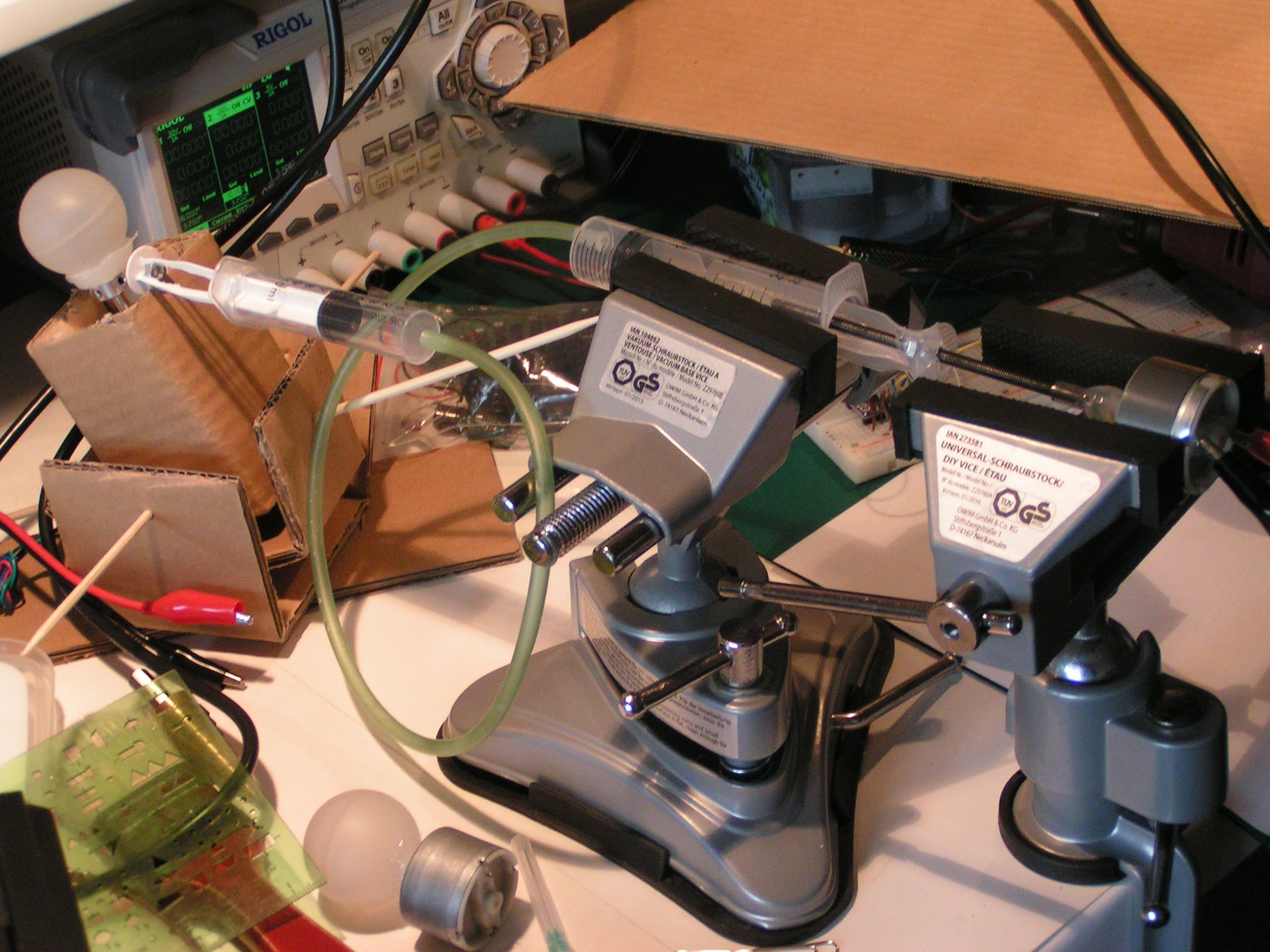
Since the driving motors are about 400 grams (14 Ounces, or Oz) each, tilting the motors will be impossible with little servos, and on the shelf linear actuators will be too big to fit on a platform. Decided to go with a DIY style linear actuators and DIY hydraulic transmission.
The intention was to have 3 different colors for the transmission fluid (colored water, one color for each motor). Went to the grocery store to buy some food grade dye. The grocery had only Blue and Yellow pigments, so I bought a bottle of Red wine as a replacement for red colored water.
I swear the missing color was not my fault.
:o)
Next step, a moving platform to study the new type of tilted balls drivetrain.
-
Never reinvent the wheel. It was already (re)invented many times before.
07/21/2017 at 21:33 • 3 commentsBummer:
"Somebody says:
It looks like you have reinvented the Hemispherical omnidirectional gimbaled wheel drive. Check out
https://hackaday.com/tag/hemispherical-omnidirectional-gimbaled-wheel/
https://en.wikipedia.org/wiki/Hemispherical_omnidirectional_gimbaled_wheel":o(
-
Parts: From Hobo to Dandy
07/21/2017 at 17:48 • 0 commentsGathering parts from all kind of electronics scrap for a PoC (Proof of Concept) is not the brightest idea, especially when there are only a couple of days left until the deadline.
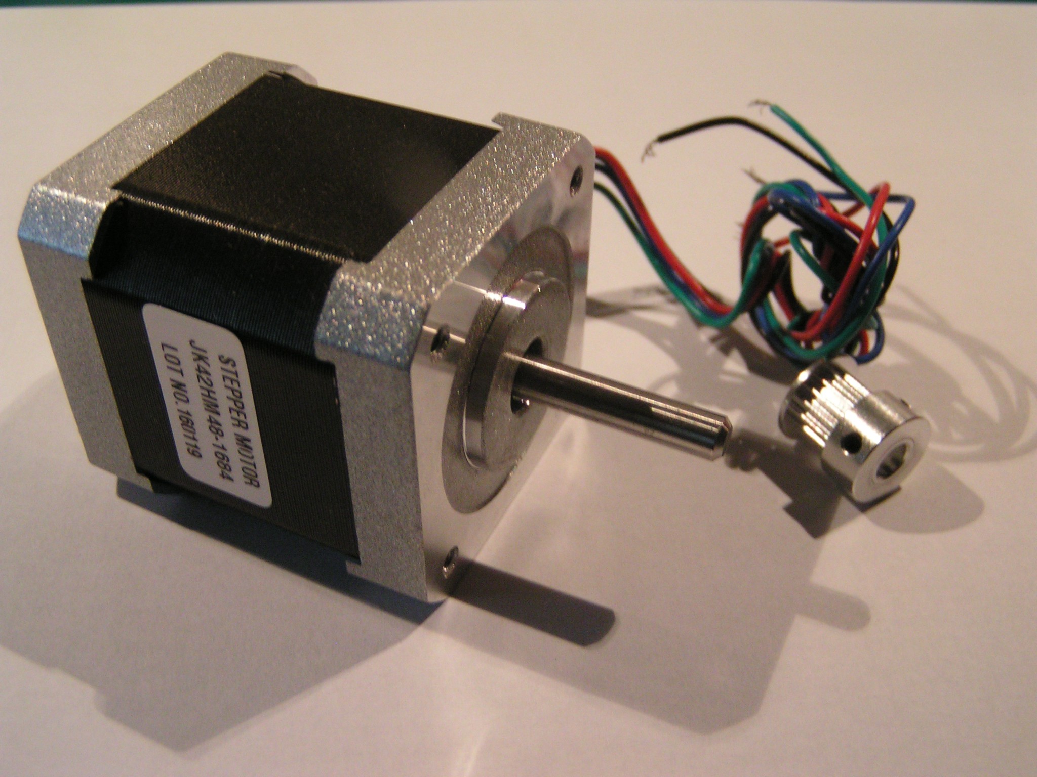
Decided to use good quality stepper motors (0.9 degree, 1.68A, 4.4Kg.cm, 3000rpm, 42mm, 2phase hybrid stepper motor NEMA17) and other parts that were destined to a 3D printer.
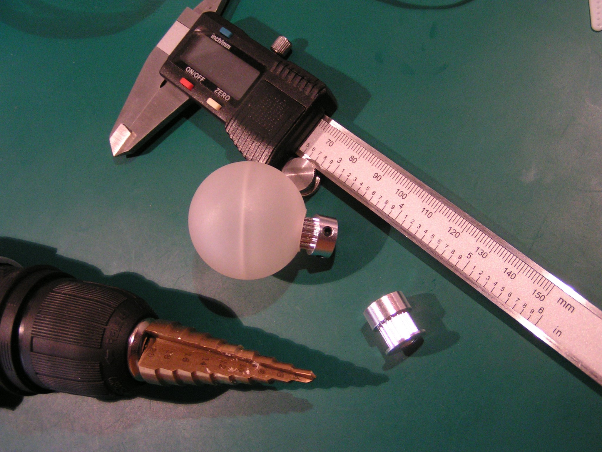
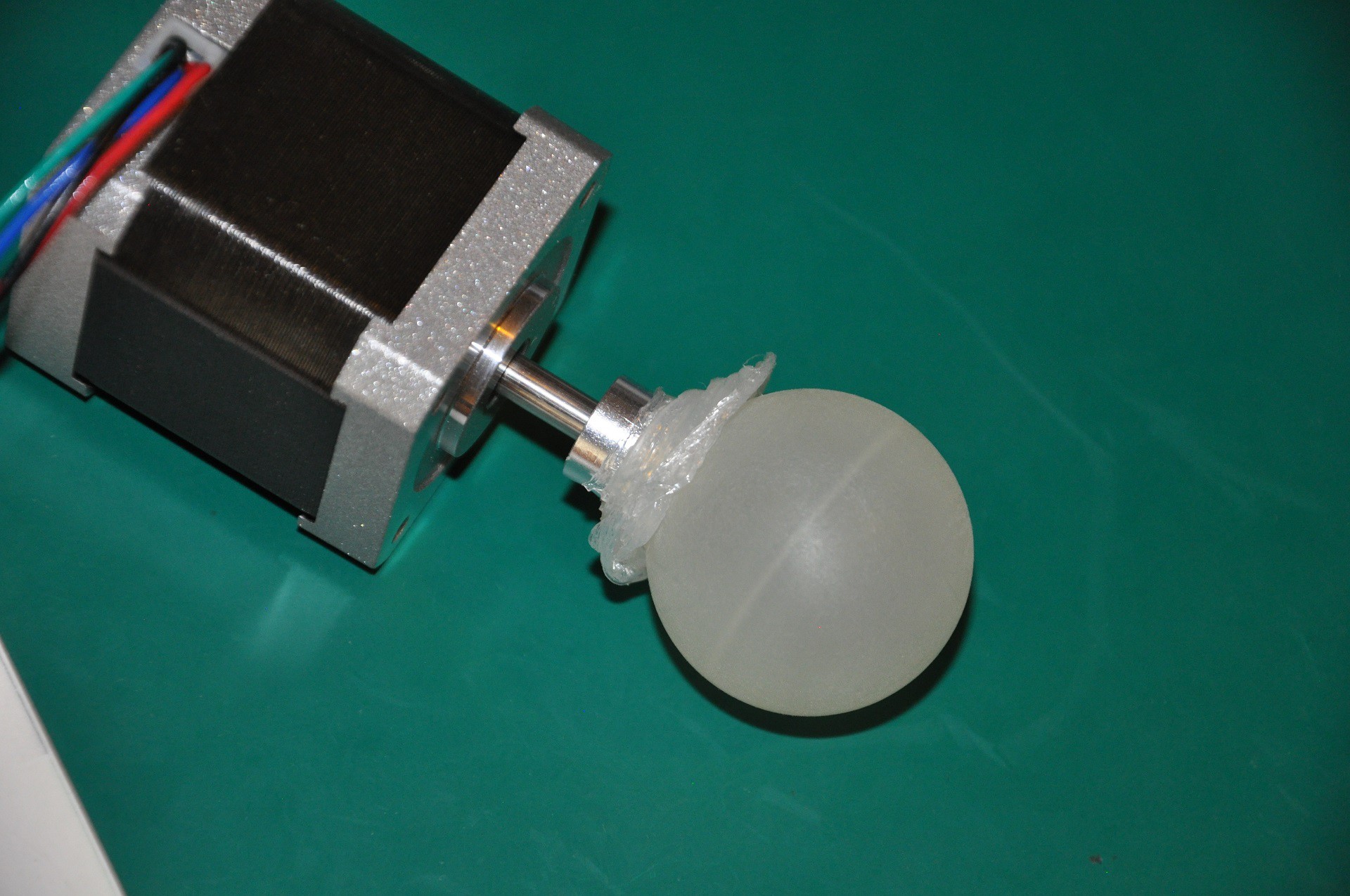
Even so, centering a ball on a motor axle is tricky.
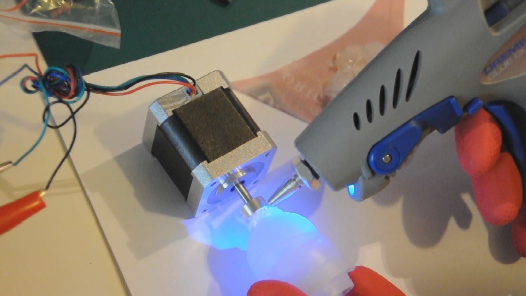
I didn't want to use a glue that can not be adjusted. First try, was with a hot glue gun:
![]()
It works, but it's not perfect. The good side is that the resulting joint is slightly elastic, protecting the motor shaft from shocks. The bad side is that the hot glued plastic can be easily pealed off by hand:
![]()
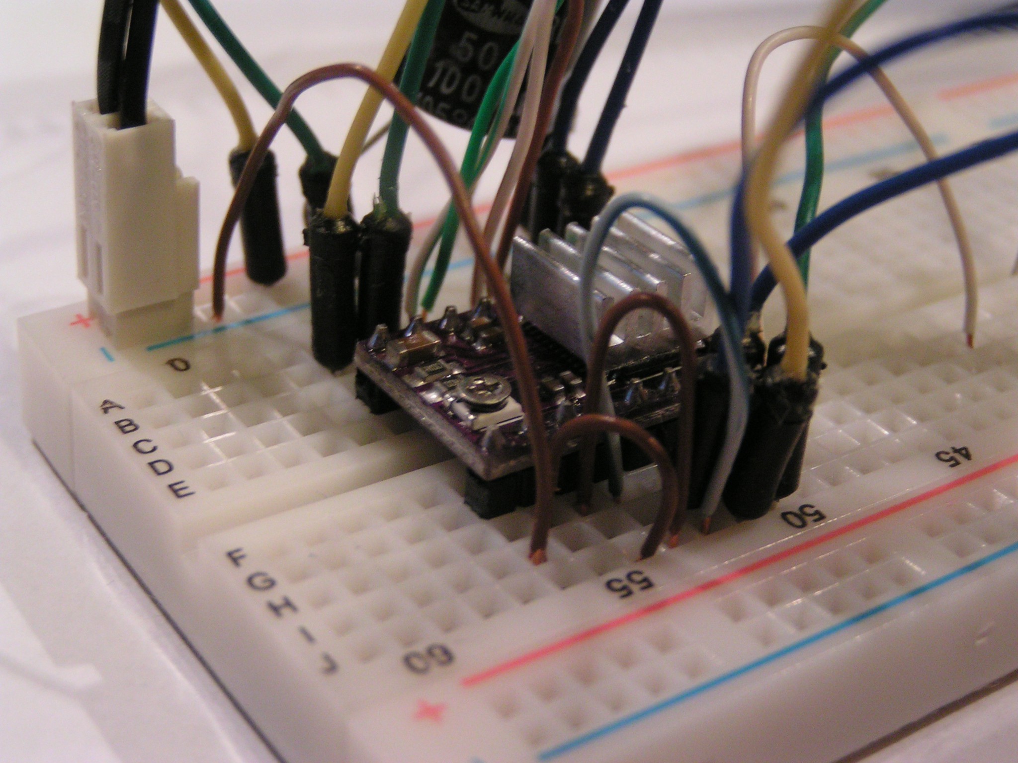
Standard stepper drivers (DRV8825) to control the stepper motors:
Three synchronously tilted balls should be able to drive a platform in any direction based on this idea:
-
Funny Motor Wants to Stand-Up
07/20/2017 at 16:48 • 2 commentsWhile was trying to see how much the RPM can be reduced while still keeping some decent torque, Lady Serendipity started to troll the experiment with a strange but funny phenomena:
The motor have a tendency to stand-up and to self-balance, apparently in a non-stable position. This is not a case of gyroscopic stabilization, the RPM is too low (motor at 2V). Also, if the RPM is increased, the self-balance doesn't happen any more.
I noticed this strange self-centering phenomena before, it was happening to other objects too (i.e. when a short flexible rubber hose is put instead of a drill bit, or the washing machine that suddenly tries to demolish the house at 1000 RPM, but works smooth at 1600). Always given them various explanations, but now I think the explanations were all wrong.
- The self-centering was noticed only in a certain RPM range, to fast or too slow, and it won't happen.
- The equilibrium happens at a certain rate of load increase, or RPM increase, then keep them constant
- If the self-centering equilibrium is lost, even if the RPM is kept constant, the self-centering doesn't happen until a new ramp-load
- All the time there is some flexible articulation involved, that allows a lot of free giggling between the load and the motorWill add 'investigate self-centering' to the bucket list, not enough time for it now.
Grrr..., I can hardly keep myself not to go for the self-centering right now!
-
Gathering Materials and Realising I'm a Fool
07/20/2017 at 10:01 • 4 commentsYesterday found a nice plastic pipe with different diameter on each size:
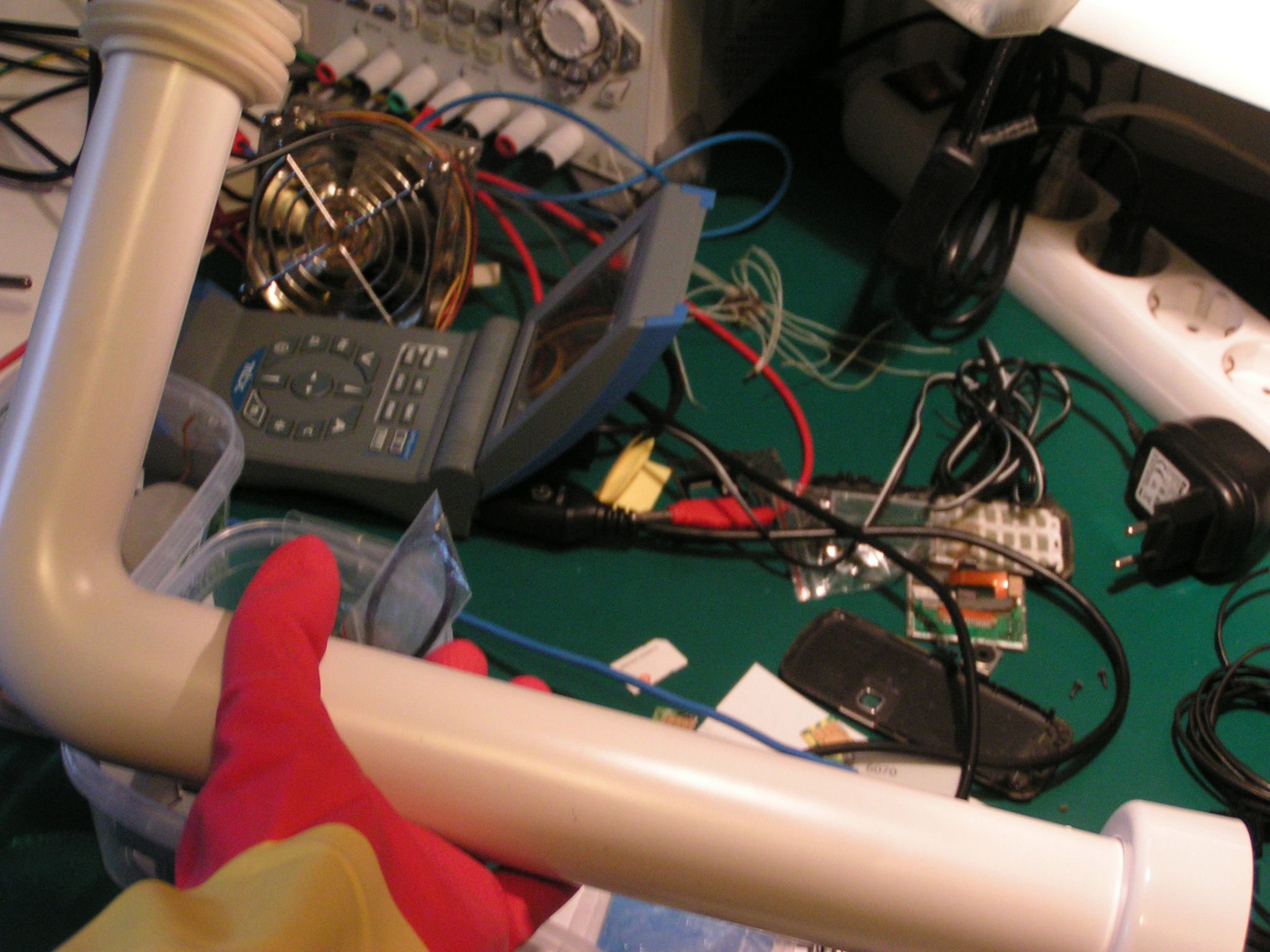
The idea was to cut 2 rings, one from each side of the pipe, then put the rings one inside the other, in order to make a gimbal type articulation, and glue the motor in the gimbal center, so the motor could be tilted.
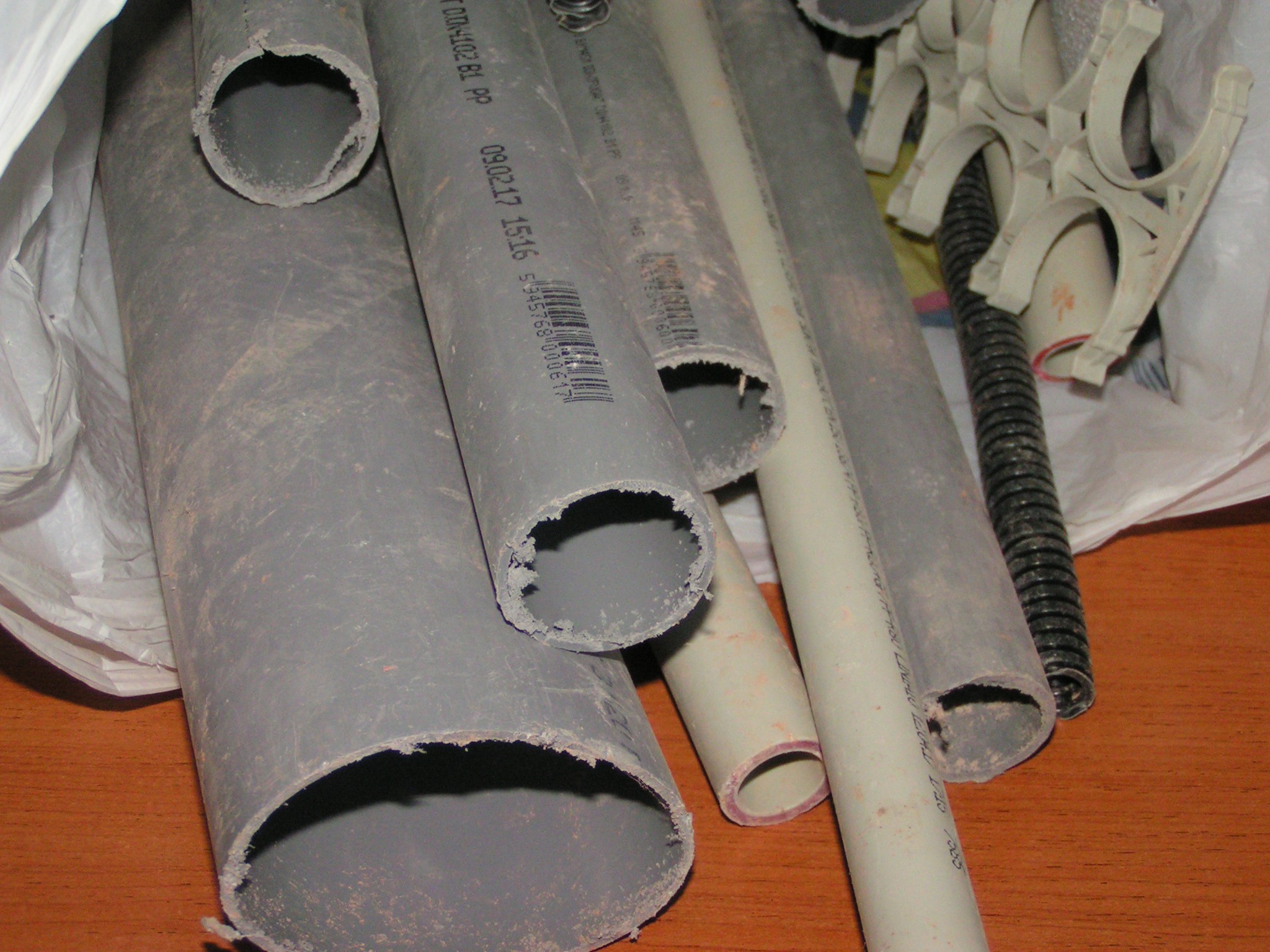
Felt like the 2 diameters were not enough, and went outside for a dumpster dive at a construction site. Found a lot of pipe leftovers, with various diameters:
This morning, started to estimate the required tilted angle and the robot speed for a given RPM. That was the epiphany moment.
I'm a complete fool because: the motors are from a cassete-tape player. A cassete-tape player moves the tape with a rod of about 2 mm in diameter. The tape speed is 4.76 cm/s. So, if the robot will have a wheel of 2 mm in diameter, it will travel just fast enough, with about 5cm/s. But the ball is about 40 mm in diameter, this will be too fast. Even more, in the cassete-tape mechanic, the motor turns the capstan rod through a belt, and that belt reduces the RPM about 6 more times.
In conclusion, for the same motor with a 40 mm ball direct-drive, the robot will have a top speed of
4.76 cm/s * 6 * 40 mm / 2 mm = 5.7 m/s = 18.7 feet/s
Way too fast, damn!
Bad robot.Failed to give him a drivetrain, better I should give him a nice name instead.
:o) -
Parts Scavanging
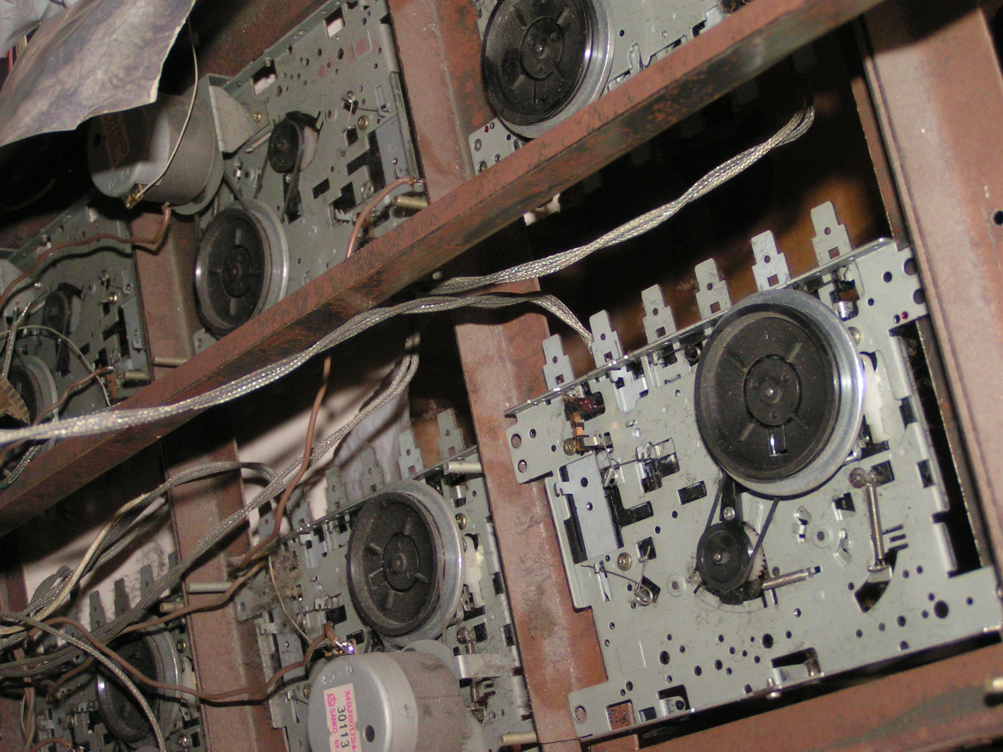
07/19/2017 at 13:07 • 2 commentsElectric motors are from an old rusty rack full of cassette-player mechanics. Motor model is SANKO, 6V, CCW, stabilized RPM. Google doesn't know much about the motor datasheet, must calculate the RPM, or at least measure it.
.
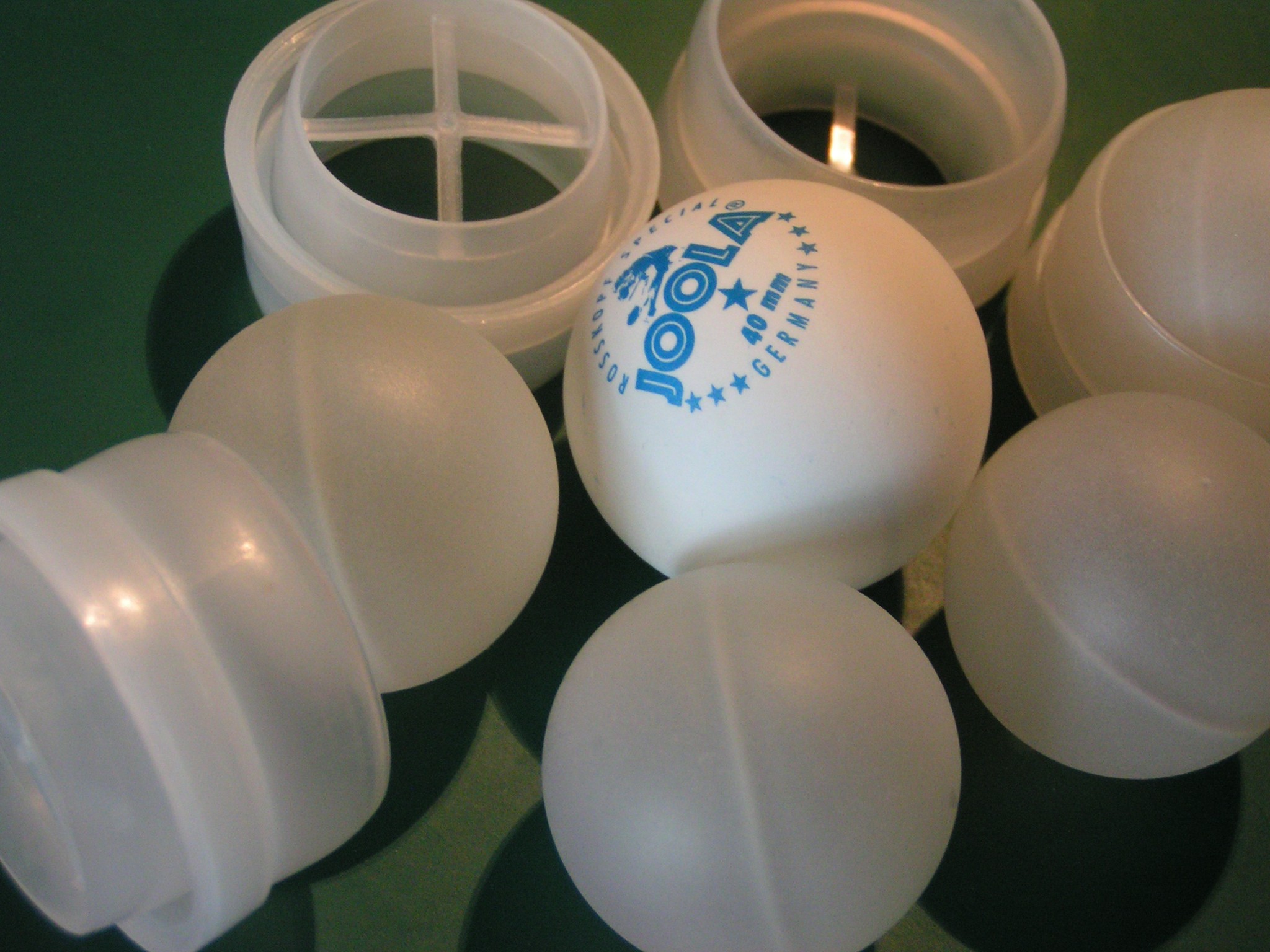
The balls are about the size of a ping-pong ball, but made out of 1-2 mm thick plastic instead of the brittle celluloid. They were initially scavenged from a roll-on bottle, in order to be used on a some 2 wheels platform as a replacement for a 3'rd caster wheel.
The Robot with Balls Experiment
A new kind of gearbox. Holonomic transmission, direct-drive and continuously-variable. From reverse to full-forward, and in any direction.
 RoGeorge