The design of the robot aims to keep the weight of the motors at the top of the leg, this is to keep their moment of inertia low so they can be swung back and forward quickly, improving the robot’s agility
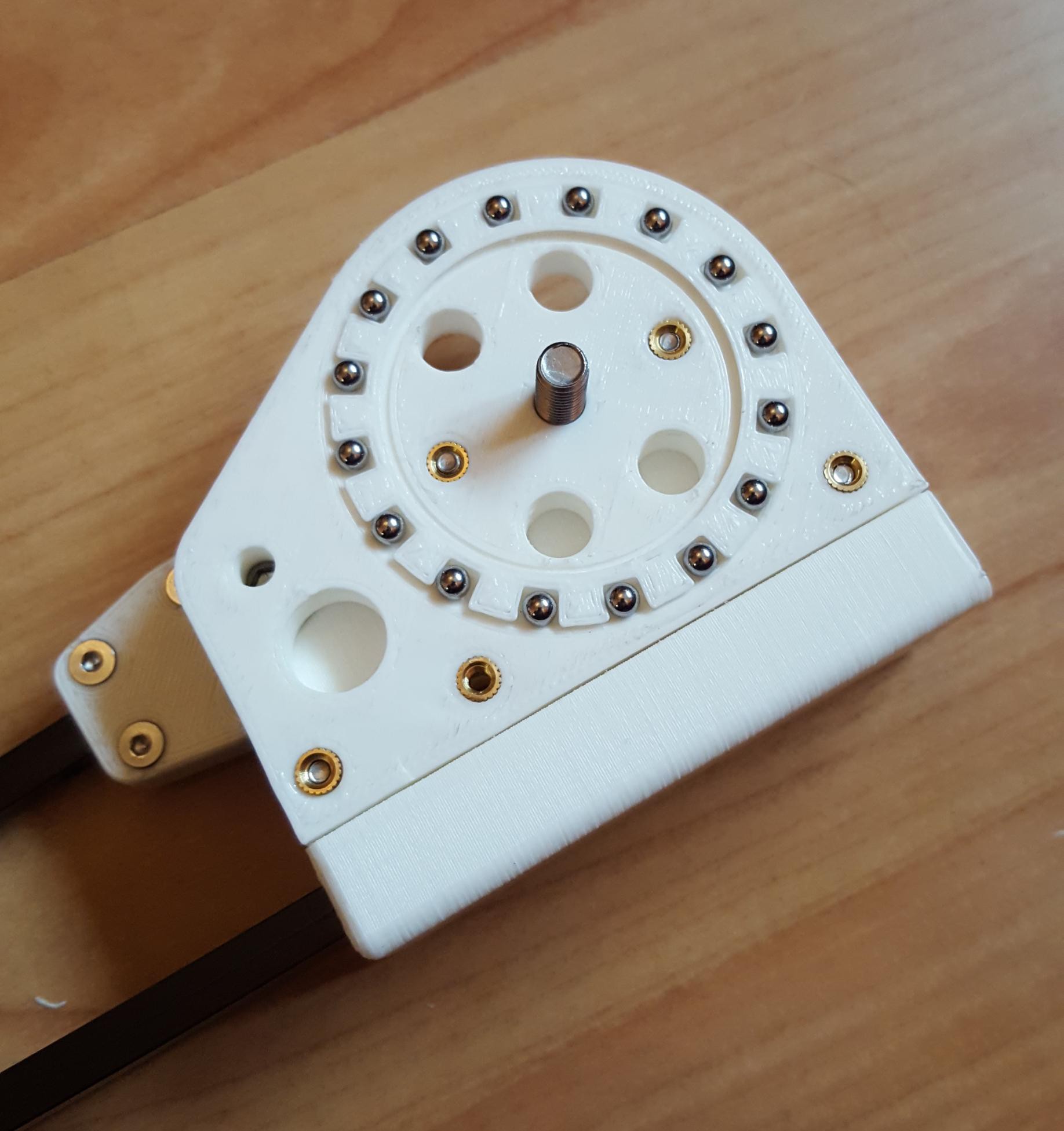
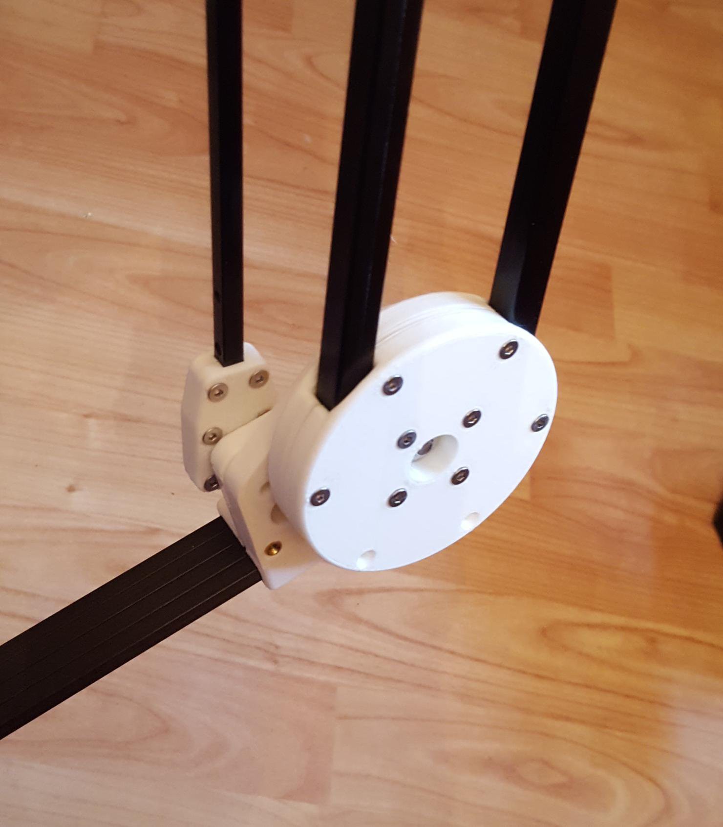
The knee joint is another place that has to pivot whilst taking bending forces. The design ended up using both off the shelf bearings for the vertical load, in combination with another plastic bearing to take the bending forces.
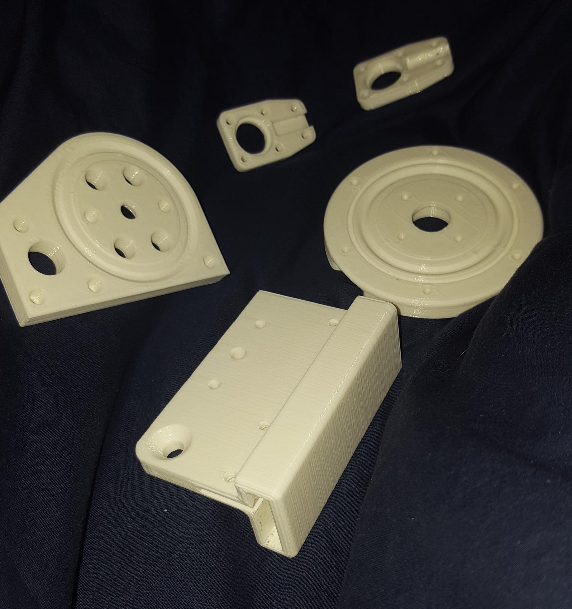
The parts of a knee joint
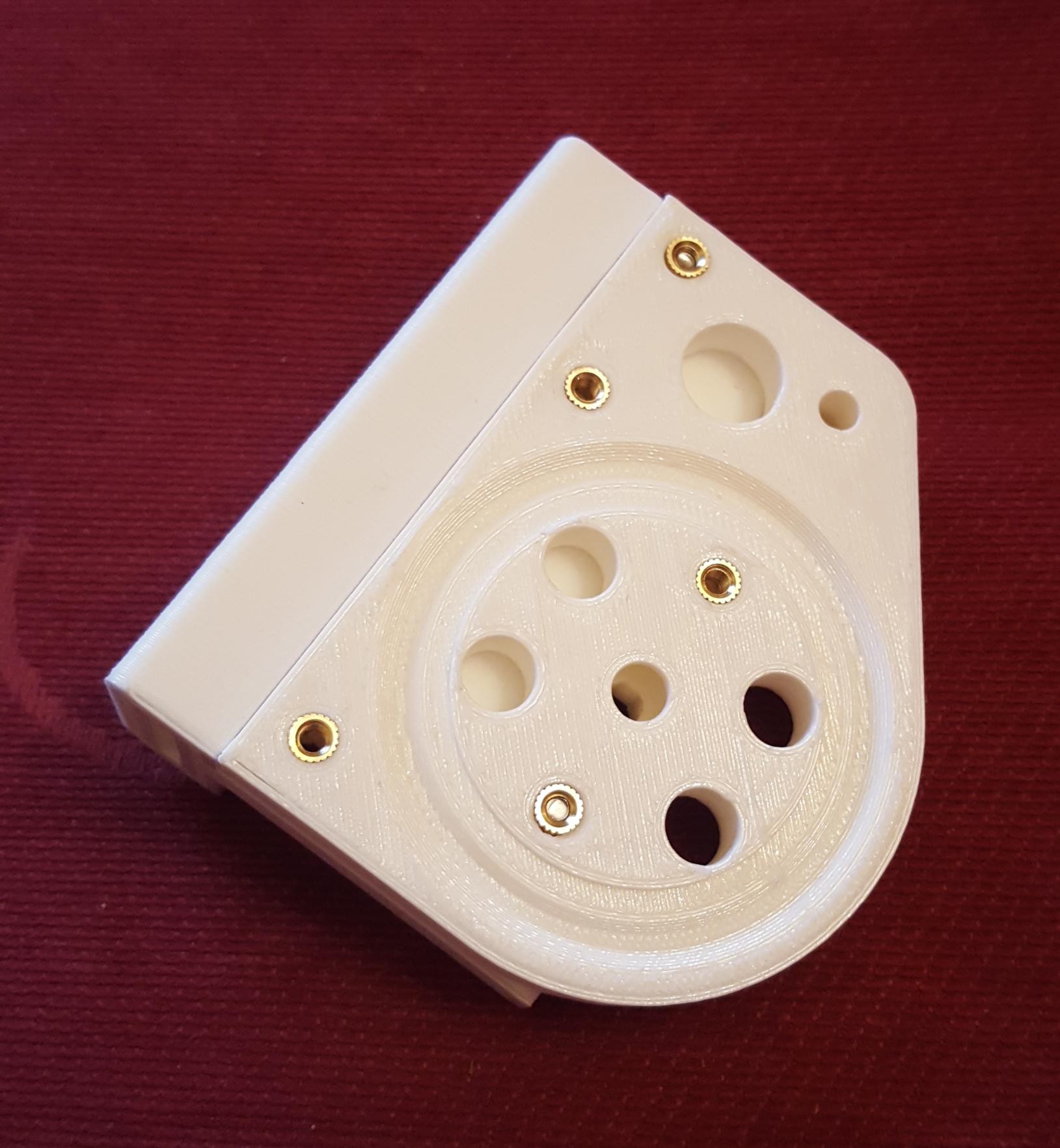
Lower half of the knee
The lower half of the knee with bearing cage and ball bearings.
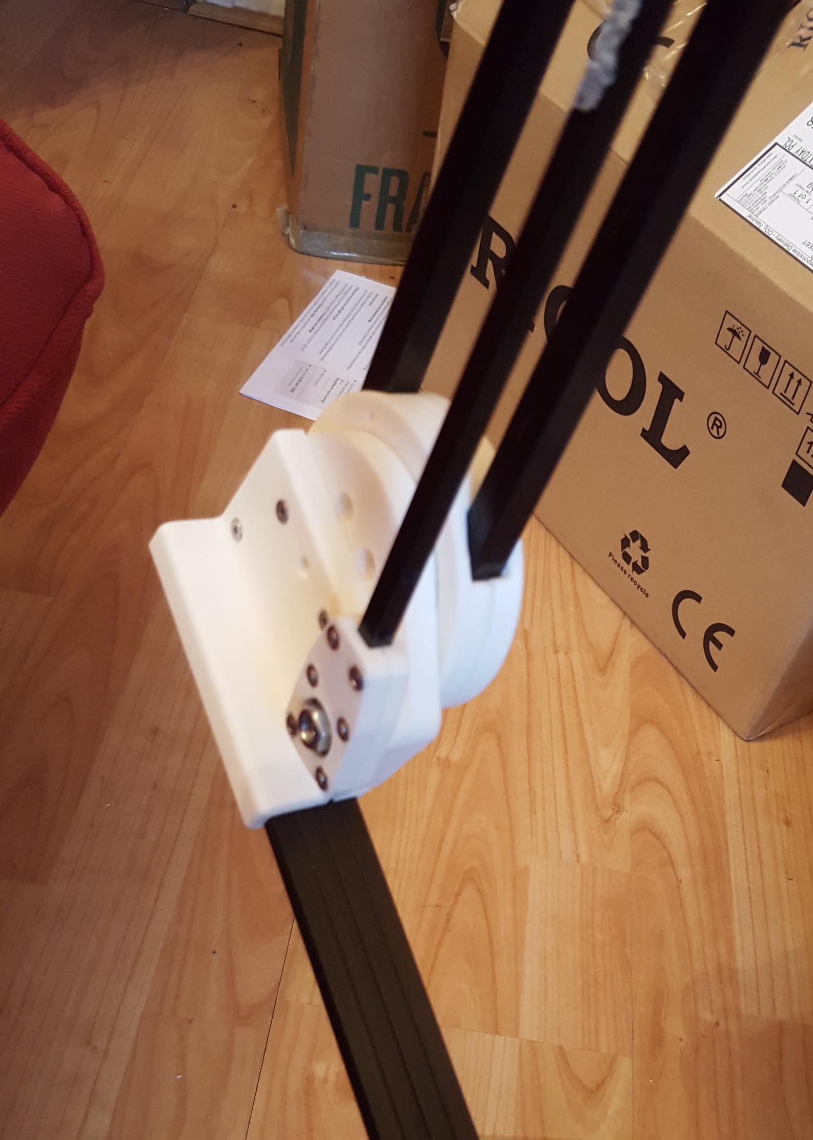
The assembled knee
 Charles Galambos
Discussions
Become a Hackaday.io Member
Create an account to leave a comment. Already have an account? Log In.