Close
0%
0%

Anti-Papparazzi Hat

A wearable optical surveillance detector

Similar projects worth following
My idea is to implement a device for detecting lens systems (camera, binoculars...) directed towards it.

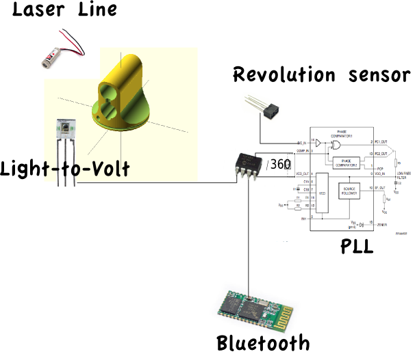
It will rely upon the assumption that such optical systems function as retro reflectors. A rotating head will emit a laser line and detect reflected light.

The direction of the detection is recorded and sent to a mobile phone for alarm and display.


System Design:

The rotating head is 3D-printed. Mounted on a slip ring. The head is rotating with the help of a salvaged cassette player motor and a rubber band.

The laser line module is mounted in the head such that the line is vertical. The detector is also mounted in the head.

Every revolution of the head is detected by a IR-reflex detector. And the resulting frequency is multiplied by 360 with a 4046 Phase-Locked Loop (PLL) IC.

For divider in the PLL the timer/counter module in a pic12f683 is used. That micro controller is also responsible for reading the counter when a detection has occurred and send that value (corresponding to degrees) on a serial line.

That serial line will be connected to a bluetooth SPP module so a mobile phone, tablet or computer can be used for display system. And as a future possibility an on-line tactical map.
View all 10 components

  • Schematics

    Tomas Holmqvist08/25/2014 at 19:08 0 comments

    I've just added an initial rendering of what's on my breadboard for the moment (omitting all unused components :-).

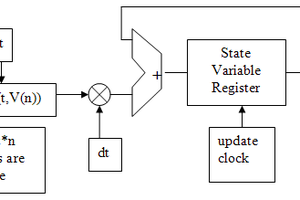
    Component values are to be decided. Right now the PLL takes about 30 sec to get into lock, a little to long time for my taste. I assume the rotational speed of the scan head will vary when carried around mounted on a hat. So the PLL probably needs to be a little more agile. I'm also not sure if I drew the feedback filter the same way as it is connected...

    There is also a first draft of layout and routing of a board. I've not yet decided if this will be a custom board or just built on some veroboard, so I've tried to keep most connections "in line".

  • 4th time is the charm

    Tomas Holmqvist08/21/2014 at 00:57 0 comments

    The instructions were to have at least 4 log posts. So here goes...

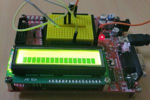
    Everything is built on a breadboard. Schematics will come but only exists in my head for the moment. There is nothing that couldn't be deduced from the system design except perhaps for the revolution sensor that is darlington connected for amplification and fed into a comparator with hysteresis feedback. There is 3 unused comparators in that capsule so perhaps I will use one of them for conditioning the main sensor.

    The main sensor isn't yet mounted in the head so I haven't been able to determine the viability of this project yet. Is the emitted laser light enough energy and in the right wavelength to get a retro reflex? Is the sensor sensitive or fast enough to detect the reflex?

    Other things on the todo-list is to build a lock-detector for the PLL and only turn on the laser when the head is actually spinning (a tiny bit more eye friendly) and implement an app for the phone.

    Another display solution could be to map detections onto a led ring that the user wears on the wrist as a watch.

  • Bitbanged uart

    Tomas Holmqvist08/21/2014 at 00:34 0 comments

    I will try to explain some small quirks in the software implementation of the uart.

    First looking at it it loads a value of 9 into a variable "putch_cnt", but the comment says "1 start bit + 8 bit + 1 stop bit" which is 10. The reason is that the loop-checks are done at the end of the loop not in the beginning, compare do...while(); and for(){...} loops in C. On the first iteration the counter is 9 and on the last it is 0, but the loop exits only when the zero:th iteration is executed.

    The variable containing the output char is used as a 1-bit 8-deep shift register. 

    Before going into the first iteration the Carry is set high, to eventually output a stop bit, and output pin is set low, to output a start bit.

    The first part of the loop a bit delay busy-wait inner loop.

    Then the next bit value is shifted into the carry flag (thereby shifting the "stop bit" into the "shift register", and that will come out again on the last iteration.

    The carry flag is double checked to avoid glitches in the output.

    The loop counter is decremented and te loop starts over with the bit delay.

    Due to the delay in the beginning of the loop the last iteration (stop bit) will get no delay, so an extra delay loop is placed afterwards together with some 2-cycle NOPs (goto $+1). The extra delay is to make sure that the stop bit is the same width as all other bits.

  • Divide by 360

    Tomas Holmqvist08/20/2014 at 23:29 0 comments

    This will document some decisions on the divide by 360 function in the mcu.

    I wanted the reaction time to a full 360 count to be as small ass possible, to minimize the jitter to the PLL comparator that will introduce oscillation in the feedback loop.

    As the value 360 is greater than 8-bit max (255) an 8-bit timer would need some software bit extension to make it a needed 9-bit, with some cumbersome reloading of counters. Also the Capture/Compare/PWM module is connected to timer 1 and that looked from the onset as a function that would be useful.

    That is why I choose to implement the counter on timer 1, as it is 16-bit wide. It is configured in external synchronous clock mode. I would like to use asynchronous mode (again to reduce jitter) but it is not recommended for use with the compare module.

    To count 360 pulses the Capture/Compare/PWM module is set in compare mode, with an interrupt generated when timer 1 is equal to 360. The hardware is responsible for resetting timer 1 to 0.

    An alternative would be to preload the counter with 35535-360 and use the counter overflow, then the CCP-module could be set to capture mode upon receiving a detection, but I couldn't get it to work that way. It would also mean that timer 1 would have to be reloaded on every overflow and perhaps the value trimmed to account for the delay of reloading the timer.

    To further minimize jitter the compare interrupt is the only interrupt. Serial communication is bit-banged in a bussy-wait loop. The "interrupt-on-change" function is used as a SR-latch on the detector input but isn't allowed to actually interrupt the processor.

  • Sources available

    Tomas Holmqvist08/20/2014 at 15:08 0 comments

    I have made the sources for this available at github. https://github.com/LeHonk/antipaparazzi

    And hopefully will be making a video tonight just minutes before dead line :)

View all 5 project logs

Enjoy this project?

Share

Discussions

James Barber wrote 08/25/2014 at 19:56 point
I like the idea...but for something like this, passive prevention would probably work better (and simpler) than active prevention. If you were to simply mount several IR/UV leds on a pair of glasses or a hat, you wouldn't have to worry about images being taken of the subject sheerly for the fact that the leds would in essence destroy the captured image.

  Are you sure? yes | no

Tomas Holmqvist wrote 08/25/2014 at 20:10 point
Of course, or a simple hoodie to hide under.
But why take the easy road? The actual reason for me doing this is to see if it is possible to cheaply implement something like this.

  Are you sure? yes | no

Similar Projects

Does this project spark your interest?

Become a member to follow this project and never miss any updates