Marius Taciuc
-
Latest HW modifications after the testing session
11/08/2017 at 04:06 • 0 commentsDuring the testing sessions, when I was increasing the output power above 30W, sometimes the MCU would reset and I was seeing this in a jam of the chars on the display. I realized that I made a mistake in the design of the layout and that would be routing the power trace too close to the MCU and too close to the 3.3V line. When I calculated the voltage per meter for some traces, I was shown values of almost 5000V/m and clearly this is not so good for my EMC.
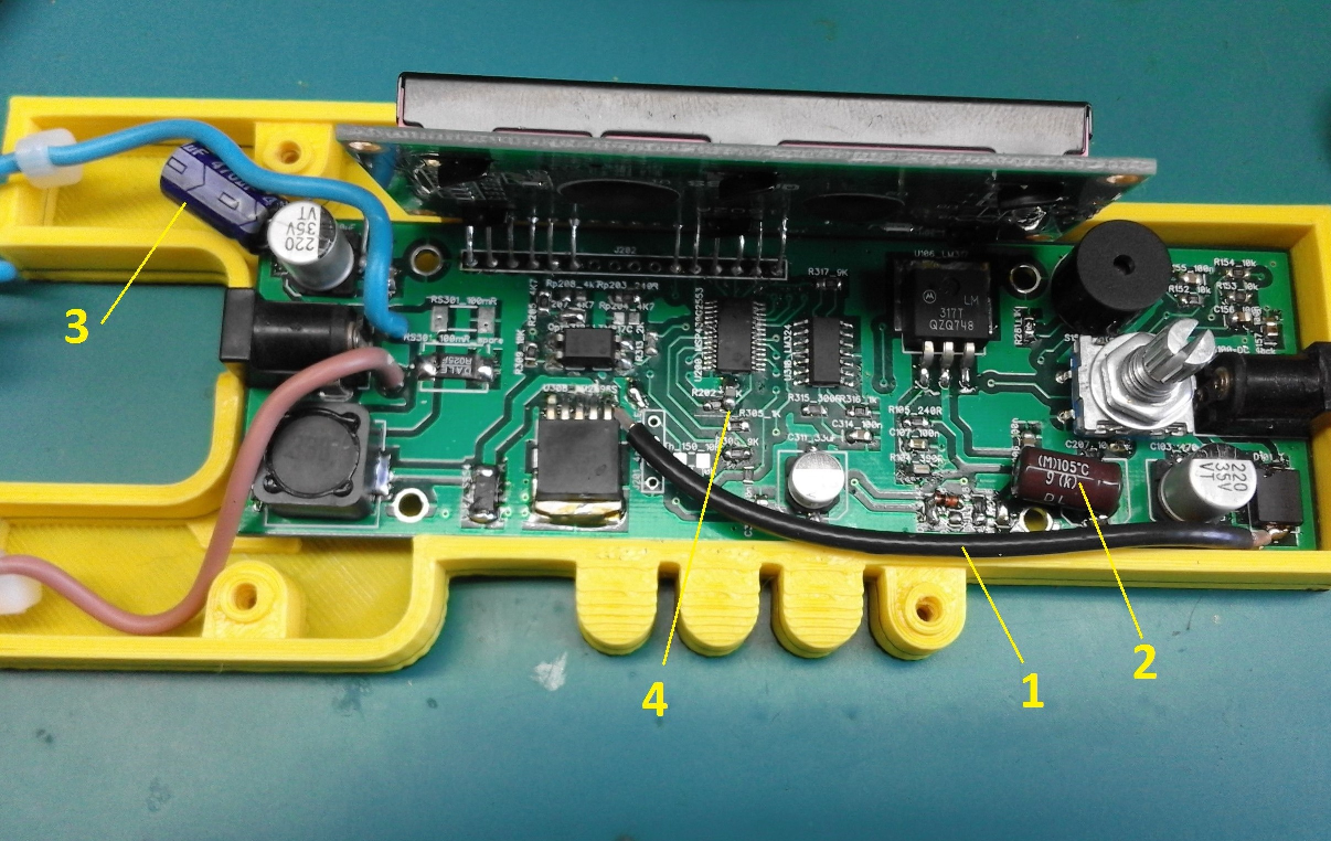
The HW modiffications I did are the following:
1. Cut the power trace on the bottom side of the PCB and replaced it with an external shielded cable
2. Replaced the output cap of the LM317 with a 470uF one.
3. Doubled the size of the output filter
4. Placed a 100nF cappacitor in parallel and very close to the MCU
Now it works like a charm and with this firmware, I managed to output a maximum power of 45W out of it. The efficiency is very good and the LM2596 does not heat above 40C, which is a success. Normally, a C1 iteration of the layout should be created after the first series of tests. Stay tuned for more updates and hopefully some test report posts.
-
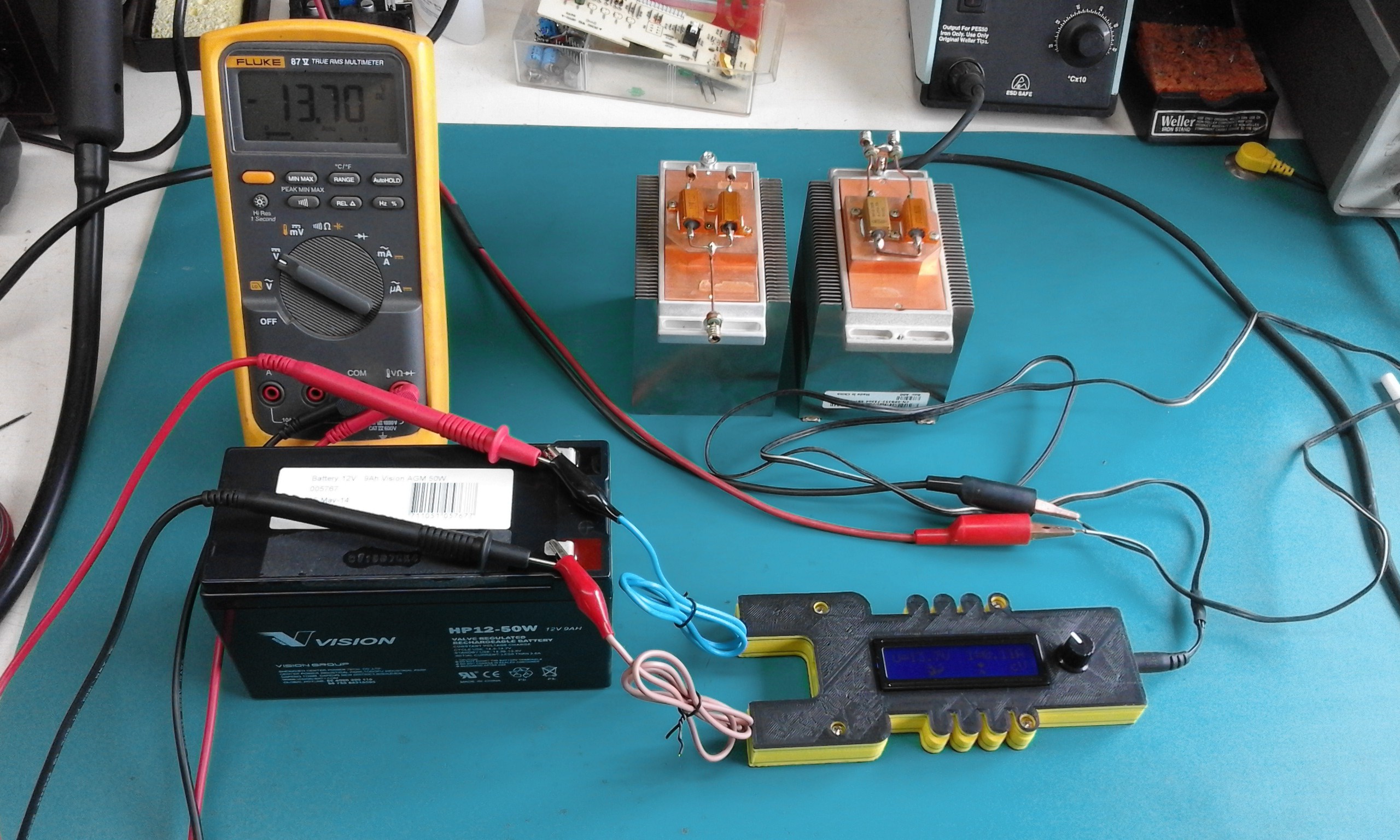
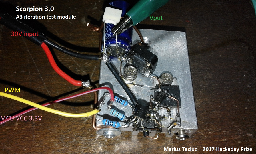
Test setup
09/28/2017 at 04:58 • 0 commentsAs I get ready to go through the testing of the Scorpion 3.0 unit, I saw as a good opportunity to upload some pictures
![]()
![]()
-
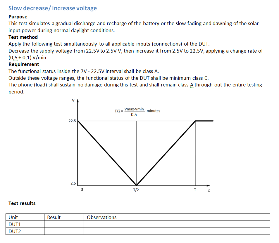
Test plan
09/04/2017 at 06:36 • 0 commentsI know I will have fun
making some smoketesting my units. I added a well made test plan for testing the Scorpion 3.0. for instance, one of the tests would be connecting a reversed car battery on the unit and another test will be the short circuit one. I will also test the unit to slow decrease and increase of the input voltage. An inside extract of this test plan looks like this: -
Added final video
08/31/2017 at 01:12 • 0 commentsFinally able to present how the actual design really looks and behaves like. I'm glad I can also show in this video a short clip with the actual 3D printing of the case. The voltage and current measurement feedback is not quite calibrated yet, as you will probably see, but the entire design looks to be very mature and stable. It's such a relief to actually have a physical device born out of nothing and to know that a couple of months ago it was just an idea in my head.
If you noticed, In this video, I actually have a newer software version than the one I uploaded on the project page. I hope to add this one too very soon.
If everything goes OK, I will start the final stage of the design, and that is testing. Watch the logs and stay tuned for updates!
-
Added A4 firmware and STL files for the case
08/25/2017 at 10:34 • 0 commentsThe A4 firmware contains all the sub menus populated into the main menu, better adjusting precision for the voltage and currents, updated component values for calculating the voltage feedback and the current and many more.
I also added another logo message that shows the "Hackaday Prize 2017" text when the device initializes.
Also, as promised, all the comments are in English. Check all the files for more details.
Have fun and stay tuned for more updates. I added a comment at the bottom of this page stating the things that are still to come. The video is also coming soon.
-
Happily presenting PCB
08/16/2017 at 23:46 • 0 commentsFinally I am able to show you the actual PCB of the design and not just a rendered image of the design.
Stay tuned for more software updates. As the design evolves, I will post more.
-
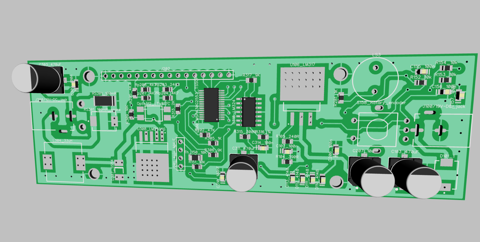
Added Layout: Horay!
08/07/2017 at 01:12 • 0 commentsIn case you are wondering who is making my PCB's, is pcbway.com.
This PCB is designed and rendered using DipTrace. Hopefully, I will be able to take out some of the heat using those viases underneath the LM2596, to transfer some of this heat to the display mounting hole and from there to the display frame that will be popping outside of the plastic case.
I will probably have to print the plastic case using a white or yellow color, just to make sure that it won't heat up if it will accidentally be exposed to sun or other external sources of heat. I hope it will work and the entire thing will actually switch 40W successfully. If everything works as desired and I will approach an efficiency of 90%, this means that I will only have to dissipate @4W on this PCB (peak wattage for a limited time) and that is OK. I made some test circuits using the LM2596 and my setup and it's all looking promising.
Until I will be able to post pictures and movies with the actual PCBs, I'll keep updating the logs and pictures with details about how I imagine the case will look like, more technical stuff, probably some software updates and more description.
Stay tuned! I'm also excited to see how the final product will look like when I will be having the case and the actual PCB fitted together. It's a nice feeling to have something physically coming to life from a simple non-material Idea.
-
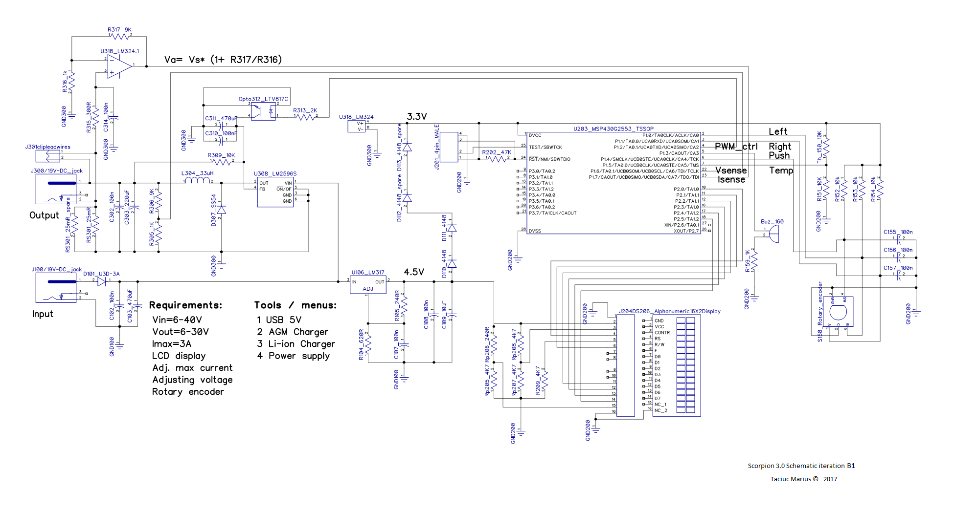
B1 Schematic upload
08/04/2017 at 03:58 • 0 commentsI managed to upload the Schematic files (also) for the B1 iteration of my project. Everything is looking so pretty now.
As you can notice, I changed the package of the MSP430. This is what I have recently purchased and I'm gonna go with it. I also replaced the op-amp with the LM324. This one has better accuracy and it promises to add less noise to my reading. I relabeled the names of the components to make the entire design more clear. I updated some component values, re-positioned the rotary encoder and added a buzzer.
I managed to test the control of the LM2596 using a optocoupler instead of a potentiometer and it works just fine. I'm not sure about the resolution it will provide and i'm not sure about the range in which I will be able to adjust the output voltage, but I'm pretty confident that I can make it work, so I'm gonna go for this design. After all, if the resolution of the PWM won't be enough, I could lower the frequency and increase the resolution. (I so have to explain this in a future post)
I think the next step would be to come up with the layout and order some PCB's.
Stay tuned!
-
Major change of plan
08/03/2017 at 01:38 • 0 commentsMajor change of
mindplanI was able to put the A3 LTspice simulation into practice and make an actual test circuit.
I measured the efficiency and I can tell you that I’m not very satisfied. The efficiency is between 0.6 and 0.7 depending on the input and output voltages. This is not very satisfying because for the final product I don’t want to use any heatsink. So, like I said, I would have to have more than 0.9 efficiency in order to achieve this.
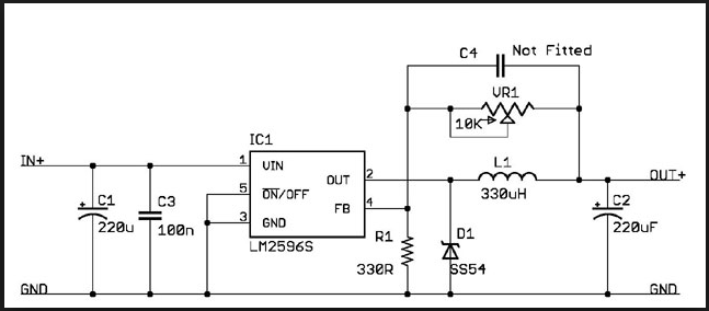
At this point is very clear to me that I won’t be able to achieve the desired slopes and switching times using a common half bridge for switching the mosfet. One good solution would be to go for a mosfet driver that has integrated half bridges and Trigger Schmidt gates. The problem is that these half bridges are usually supplied at 12V and this means that I will need another intermediate voltage regulator in my schematic.
The best solution that I’m gonna go for, is using a an integrated Buck circuit. I’m going to use the LM2596. This is the common datasheet recommended schematic that I will have to integrate into my design.
I could use the actual optocoupler PWM system that I have, to drive and control the LM2596.
Stay tuned for the schematic update.
-
Firmware upload
08/02/2017 at 03:31 • 0 commentsI uploaded the A3 firmware iteration.
I'm sorry it contains some comments that are not in English. I will modify this for further variants.
At this stage, the software contains only two of the intended four menus. In case you are wondering which tool am I using for programming the MSP430G2553, it is IAR embedded workbench. I tried Code composer, but I like IAR better.
I'm facing a problem, though: I have a low cost free licence which limits the code size to 8K. This code that I uploaded, has already more than 6K and I need to implement the other menus too. It is true that my code is not optimized yet, but I still face this challenge. If you have some ideas or advises about any other IAR cheap licence I could purchase, or if you know some other programming environment that allows me to use the maximum MCU memory, please message me.
I played a lot with the voltage divider resistor values and with the op-amp resistors, so if you find something that it's out of it's place in the mathematical formulas for calculating these values, please excuse me.
Stand by for updates.