-
5 lb bag with 10lbs of stuff in it.
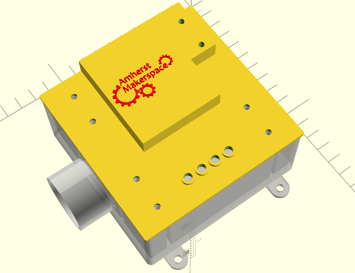
01/17/2024 at 03:57 • 0 commentsOriginally, we were planning on ordering enclosures and modifying them for the card readers and LEDs. However, I was walking through my local home improvement shop and noticed a 2 gang electrical box. Thinking to myself I bet I could make everything fit in that box.
I grabbed one, brought it home and with the help of the 3D files available on the McMaster Carr web page I was able to CAD up a box:
Yes, I use OpenSCAD. I'm a Sofware developer by day, and the tool works with the skills I already have. If you are keeping score, I use both OpenSCAD and Fritzing.
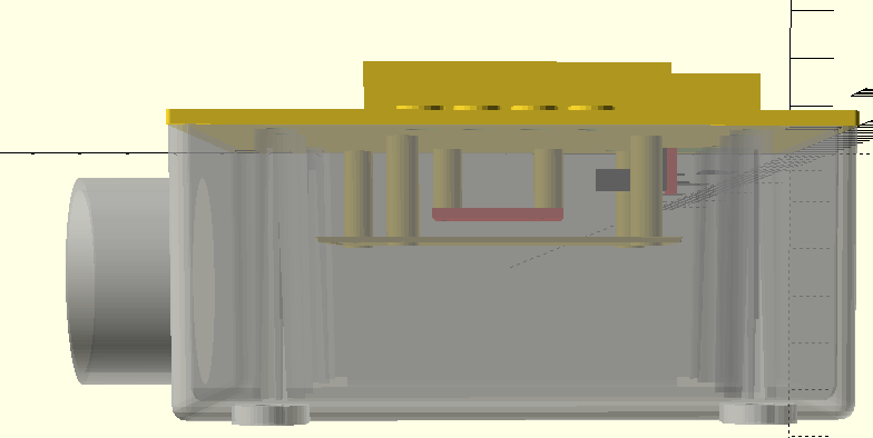
I was able to model everything inside the box with enough space to spare for wires and power. This should work, be off the shelf, available to anyone, and be cheap!
-
Getting Board with Problems
01/17/2024 at 03:46 • 0 commentsI have a control board format selected, life is looking good. In order to keep things simple we need a board to hold make wiring easy. We need to support a few functions:
- Easy mounting of the ESP 32 board.
- Level Shifters so that the 3.3v ESP 32 can work with 5.0v logic devices.
- An input button that can be pull-up or pull-down.
- Easy access to a relay output, a card detection method, Reset button, and LED status indicators.
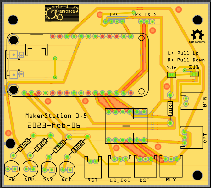
We wanted minimal population effort. The board is designed to take a common 4 channel bi-directional level shifter board and the rest of JST connectors or direct wire holes for the relays and buttons.
I know many people hate Fritzing, and I see all their issues. I learned it a long time ago, and it helps me go from breadboard to circuit board. I'm working on learning some of the alternatives out there to do more advanced work.I know!
It is ugly. it is inefficient. The routing is ham fisted at best. But it is my ugly baby and I'm proud of it anyway!
Yes, and you are reading that correctly, version 0.5. It took me 5 tries to make this monstrosity. I learned a lot along the way.
Version 0.1 attached to a Raspberry Pi, which is a hardware system we abandoned.
Version 0.2 should have been tested on a breadboard first, I forgot that some pins were input only, and used them for the LED outputs. That is why some of the LED lines run clear across to the far side of the board, not all the I/O pins are input and output and I had to do some odd routing to compensate.
Version 0.3 Worked better, but we found that for the confirmation button we needed pull-up or pull-down capabilities, so we added the pads so we could configure it at implementation.
Version 0.4 The board was too cramped. We didn't fabricate this one, it just didn't fit right.
Version 0.5 The board was sized a bit better and we added a breakout for the Reset pin on the board.
-
Float like a feather and string like a USB.
01/17/2024 at 03:29 • 0 commentsThe ESP 32 devices come in every shape and size imaginable! If we are going to have any hope of a future capable design we need some kind of standard to work with. Both Sparkfun and Adafruit sell several flavors of device on a form factor called "Feather". We are thinking if we design around this format, then we should be able to use any device that is Feather compatible. It is as close to a standard as we can find.
The next problem is the pin outs. I happen to have three devices that are all feather boards, all different flavors of ESP 32 and they have slightly different pinouts. Power and Ground are fine, but the I/O pins are different. In the Arduino Software we are going to have to include a way to flag which board we have and use #Defines to select it. Here are the three I have already:
//Sparkfun ESP32 THING Plus WROOM / Adafruit HUZZAH32 ESP32 Feather #ifdef ESP32ThingPlusWroom const String Board = "ESP32ThingPlusWroom"; const int HBPin = 13; //Heartbeat LED OUTPUT const int APPPin = 12; //Approved LED OUTPUT const int DNYPin = 27; //Denied LED OUTPUT const int ACTPin = 33; //Active LED OUTPUT const int OPTPin = 36; //OPTO INPUT const int BTNPin = 39; //BTN INPUT const int RLY = 19; //Relay OUTPUT const int DTS = 18; //DST OUTPUT const int LS = 5; //LS OUTOUT #endif //Sparkfun ESP32-s2 THING Plus WROOM #ifdef ESP32S2ThingPlusWROOM const String Board = "ESP32S2ThingPlusWROOM"; const int HBPin = 13; //Heartbeat LED OUTPUT const int APPPin = 12; //Approved LED OUTPUT const int DNYPin = 11; //Denied LED OUTPUT const int ACTPin = 10; //Active LED OUTPUT const int OPTPin = 7; //OPTO INPUT const int BTNPin = 9; //BTN INPUT const int RLY = 37; //Relay OUTPUT const int DTS = 35; //DST OUTPUT const int LS = 36; //LS OUTOUT #endif //Adafruit ESP32-S2 Feather #ifdef ESP32S2Feather const String Board = "ESP32S2Feather"; const int HBPin = 13; //Heartbeat LED OUTPUT const int APPPin = 12; //Approved LED OUTPUT const int DNYPin = 27; //Denied LED OUTPUT const int ACTPin = 33; //Active LED OUTPUT const int OPTPin = 36; //OPTO INPUT const int BTNPin = 39; //BTN INPUT const int RLY = 19; //Relay OUTPUT const int DTS = 18; //DST OUTPUT const int LS = 5; //LS OUTOUT #endif -
The big BOM
01/17/2024 at 03:22 • 0 commentsThe initial project was designed around a Raspberry Pi 2, and later the 3. This was during the time that Arduino didn't have a Wi-Fi option, a time before the ESP series of device changed the face of the IOT world. We also anticipated the need for a user interface, however we never had need for it, and decided to remove the requirement. The also the price, the PI, the wiring, the enclosures, the power requirements, they all resulted in a Bill of Materials (BOM) that was high, and with the dirty power in the building we had SD cards burning out and locking us out of the machines.
We needed a simpler system. Fewer bells that never rung. So, a redesign around the ESP 32 board should give us what we need, a simpler system, and a lower cost per system.
Back to the drawing board.
-
Drastic times call for Drastic Redesigns
01/17/2024 at 03:17 • 0 commentsThis project has gone stagnant, and it is due for some significant updates. Technology has changed, the Makerspace needs have changed, and the system has to change to match. I'm going to create a series of Project Log entries chronicling the process of the redesign. This is all done retrospectively, so I may miss one or more of my numerous stumbling blocks on the way, but I'll do my best to document them all.
-
Maker Over Ethernet
07/29/2017 at 22:42 • 1 commentWith about 20 machines needed network, power, and the ability to activate the dust collection, air filter or other support systems we need a simple way to wire that all across the large space. Power over Ethernet is a thing, but it is costly and doesn't have the system activation detect capabilities we want. So we have designed Maker Over Ethernet.
It is a simple breakout board that takes network, power, and activation detection and passes it over a standard CAT6 cable. Network only requires 4 of the 8 wires, leaving two pairs for power and activation detection.
We also used some RJ-45 connectors from SparkFun https://www.sparkfun.com/products/643
and some JST connectors: https://www.sparkfun.com/products/9914
Amherst Makerspace Maker Station
A system to manage makerspace members access to equipment