 GeekLab
-
1Making an Adapter and Power source for the ESP-01
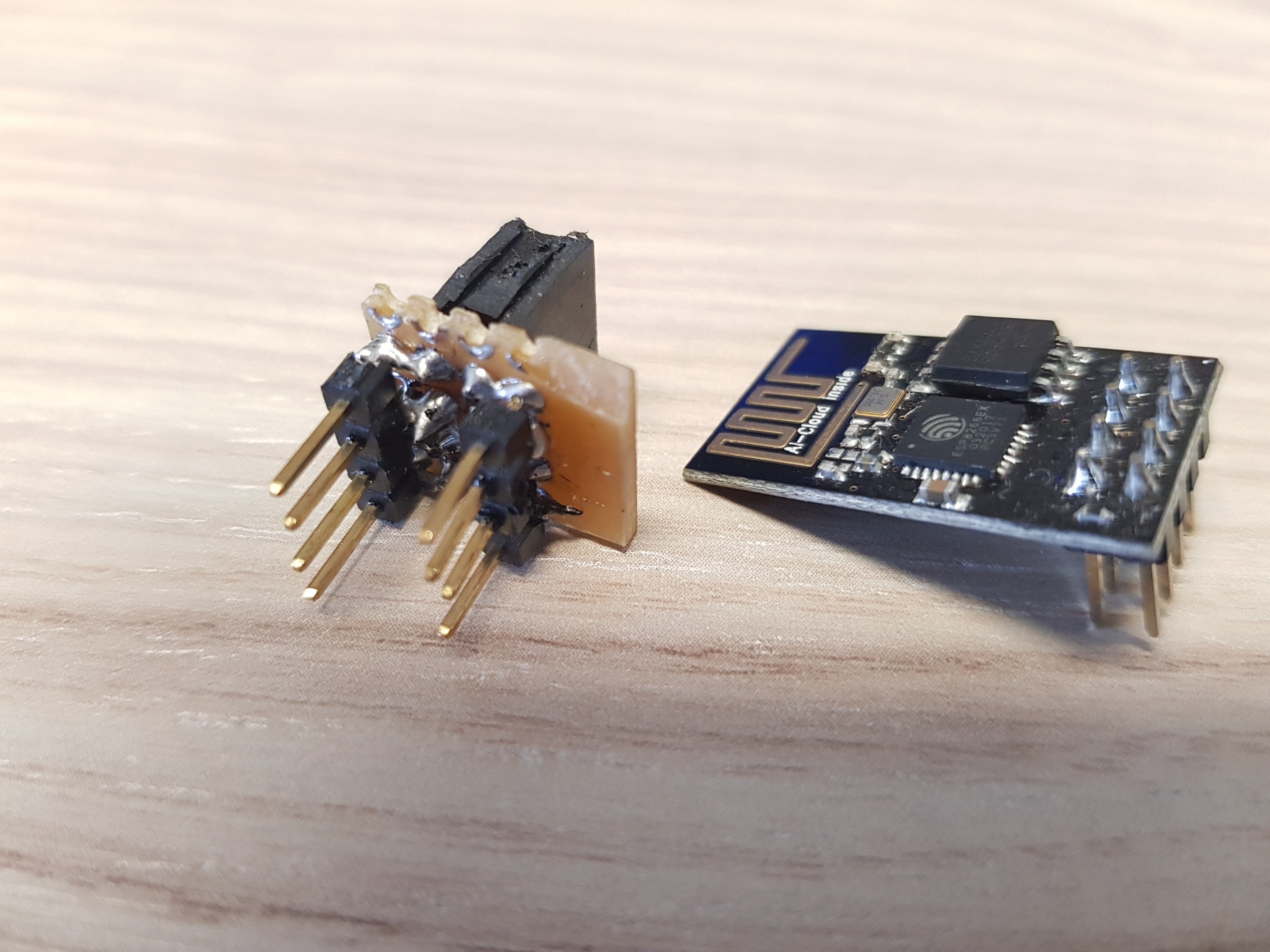
Looking at the 01 version we see that it is not very breadboard friendly so we have to make an adapter for programming. You could buy one on ebay for a few cents but waiting one month just for shipping is silly because you can make one in 5 minutes.
![]()
I made my adapter using male and female headers soldered on a tiny 4x4 square cut out of a prototype PCB. You could also use female to male jumper wires as many people do but I don't have them. As a last resort theoretically you can just solder wires to it (like we will have to do on the 12F version) but it is rather messy and you could short something.
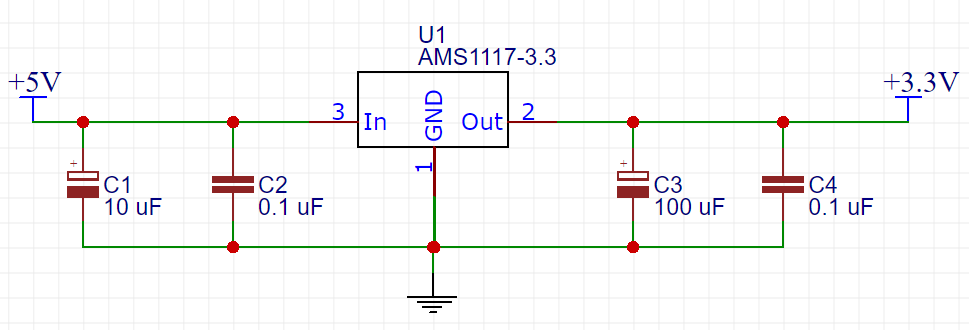
The ESP8266 runs on 3.3V and consumes anything from 20 to 250 mA so to properly power the module you must get a power supply that can deliver that amount of current or the ESP will be unstable if it works at all. Do not even try to connect it to the 3.3v pin on the Arduino or the FTDI breakout because it can't deliver that amount of current. For example if you have an old PC power supply you can use that or in my example use a voltage regulator, because I will fit these module in my wall switch so it has to be a small one. The AMS1117 3.3V version is the perfect coise, it is small and can deliver up to 1A. I have connected its input to the 5v pin of the Arduino and here is the schematics (capacitors are there for smoothing and decoupling, you don't need to use the exact same values but it's recomended):
![]()
C1 10uF - for stabilizing the input
C2 0.1uF or 100nF - decoupling, must be placed near the voltage regulator
C3 100uF - for stabilizing the ESP8266 input
C4 0.1uF or 100nF - decoupling, must be placed near the ESP8266 -
2Communication Setup
If you can successful power up the module it's time for the next step, setting up a communication to the PC. The easyest way is to use a FTDI Breakout board (link in the project components list) or using an Arduino Uno as a Serial programmer.
1. Using a FTDI Breakout board
Communication on the module is using 3.3V (it is not 5V tolerant, not even the RX pin!) so if you happen to have a FTDI breakout that has an on board jumper for voltage selection (like mine) set it to 3.3V and you can skip the 2 resistor and connect the RX line from the ESP directly to the TX on the FTDI. If your programmer uses 5V for communication connect everything as the picture shows. The resistors form a voltage drop so the 5V signal from the FTDI board gets "converted" to 3.3V.
![]()
2. Using Arduino Uno
To use an Arduino as a USB to Serial converter you must disable the onboard Atmega chip. There are 3 ways:
- Connect the RESET pin to GND or
- Upload a Sketch (The sketch basically stops the Atmel chip to interfere the communication between FTDI chip (on the Arduino board) and your other device)
void setup(){
pinMode(0,INPUT);
pinMode(1,INPUT);
}
void loop(){
}
or
- Remove the Atmel Chip (If you have the SMD version you can't do this)
The original post is HERE.
And now just instead of connecting the TX and RX line to the FTDI board as the picture above shows, you connect it to the Arduino (be sure to conncet the two resistors as on the picture because the Arduino uses 5V serial communication).
Arduino UNO - Pin 0 goes to the RX of the ESP and pin 1 to the TX of the ESP.
Pins explanation:
- TXD (goes to the 3.3V Rx of the Programmer)
- CH_PD (enable/power down, must be pulled to 3.3v directly or via resistor)
- REST (reset, must be pulled to 3.3v, not necessary but recommended)
- VCC (3.3v power supply)
- GND (connect to power ground)
- GPIO 2
- GPIO 0 (leave open or pull up for normal, pull down to upload new firmware)
- RXD (goes to the 3.3V Tx of the Programmer)
-
3Lets do it
For communication to the module we are using Arduino IDE, it's simple and it has a Serial monitor. We first need to install the ESP board so the software recognizes our board (If you have not already installed Arduino IDE you can go HERE and install it yourself, there are many tutorials online on how to do that.).
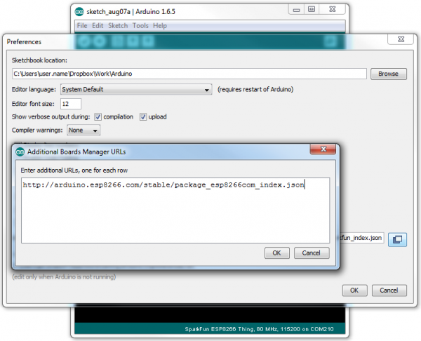
To begin, we’ll need to update the board manager with a custom URL. Open up Arduino IDE, then go to the Preferences (File > Preferences). Then, towards the bottom of the window, copy this URL into the “Additional Board Manager URLs” text box:
http://arduino.esp8266.com/stable/package_esp8266com_index.json
![]()
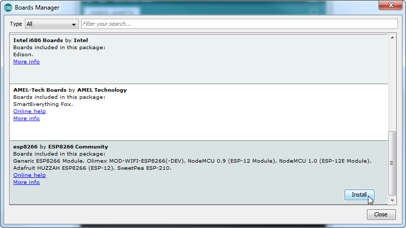
Hit OK. Then navigate to the Board Manager by going to Tools > Boards > Boards Manager. There should be a couple new entries in addition to the standard Arduino boards. Look for esp8266. Click on that entry, then select Install. It may take a few minutes to download and install (the archived file is ~110MB). Once the installation has completed, an Arduino-blue “INSTALLED” will appear next to the entry
![]()
Or you can read the full detailed tutorial.
Select “Generic ESP8266 Module” from the Tools > Boards menu, then select your FTDI’s port number (if you are programming your module with Arduino select the Arduino Uno port number) under the Tools > Port menu (if your FTDI board port isn't listed in most cases you will need to install the appropriate drivers for that particular board and there are plenty tutorials online for that.).
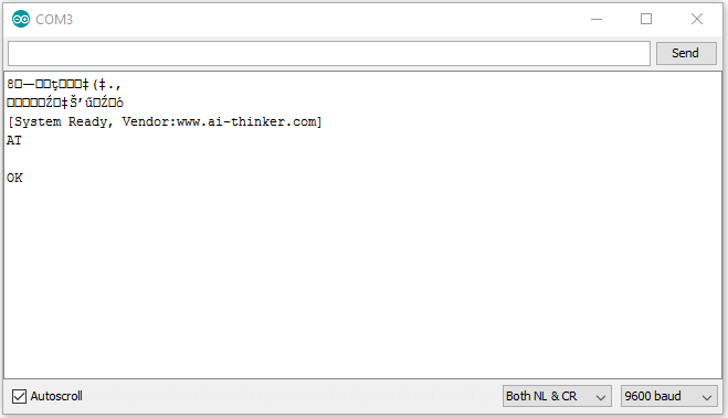
Everything is setup now, go to Tools > Serial Monitor, set the baud rate to 115200, restart your ESP8266 and there should be a "ready" message. If everything is ok when you type "AT" and press send you should get a "ok" message. With sending these simple AT commands you can control the ESP, HERE is the list.
![]()
If you try setting up the baud rate to 76800, when you power up the module it will list some debug messages, that is not the right baud rate of your board because you must find the one on witch you get the "ready" message.
-
4Troubleshooting and code examples
It doesn't always work the first time so here are a few things you should check before claiming that the board is faulty:
- If you have the ESP-01 model ensure that the red led is on (power indicator, if its off then the board does not receive power)
- Ensure that you have selected the right COM port
- GPIO 2 needs to be disconnected or pulled to VCC (3.3V) when powering up the module
- GPIO 0 for normal operation must be disconnected or pulled to VCC (3.3V) just like GPIO 2
- Check your wiring and that you have properly connected the RX and TX pins to your programmer
- Try changing the baud rate from 115200 to 9600 because not all ESP8266 boards operate on the same baud rate (this is the case for my board)
- Whichever baud rate is selected (if you didnt get the "ready" message at the end) you should always see some weird characters (garbage) when powering up the module that means the board is talking to your computer but he is set to the wrong baud rate (like on the third picture in step 3). If for whatever reason it's still not working post a comment so I (or someone else) can help you.
Caution! When you are uploading a program to the ESP8266 close the Serial monitor because sometimes the upload failes when you leave it open.
If you upload any program on to your ESP8266 board you WILL LOOSE the AT firmware and to bring it back you will have to upload it with different software (The update firmware part of this tutorial).
Here is a program that binks the onboard led, go to File > Examples > ESP8266 > Blink or copy the code below:
void setup() {
pinMode(LED_BUILTIN, OUTPUT);
// Initialize the LED_BUILTIN pin as an output
}
// the loop function runs over and over again forever
void loop() {
digitalWrite(LED_BUILTIN, LOW);
// Turn the LED on (Note that LOW is the voltage level
// but actually the LED is on; this is because
// it is acive low on the ESP-01)
delay(1000);
// Wait for a second
digitalWrite(LED_BUILTIN, HIGH);
// Turn the LED off by making the voltage HIGH
delay(2000);
// Wait for two seconds (to demonstrate the active low LED)
}
Or if you have a different version of the board (without the on board LED) copy this code that writes the "It's working!" message every one second on the serial monitor:
void setup() { Serial.begin(115200); // Start the Serial monitor on the 115200 baud rate } // the loop function runs over and over again forever void loop() { Serial.println("It's working") // Print message to the Serial monitor delay(1000): // Wait one second } -
5Let's update the ESPThis applies to all models of the ESP board.
Updating the firmware is a great way to get new features and bugs fixed, if you bricked the ESP you can unbrick it or get back the AT firmware you have lost while uploading some other code to it. My tutorial is an updated and simplified version of this.
So let's get started:
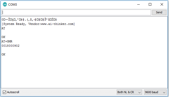
Open up the serial monitor in Arduino IDE, type AT and press Enter on your keyboard; if all is well, the ESP will respond with OK in the Serial monitor window. If it does, breathe a big sigh of relief because you have just cleared a major hurdle. If it's not working check out part 4 of this tutorial (Troubleshooting).
Next, type AT+GMR and press Enter. The ESP should respond with something very similar to the window below:
![]()
The AT+GMR command tells the ESP8266 to report what version of the AT command set it contains (in this case its 9.2). Finally, as usual, the ESP8266 concludes its transmission with OK.
If the ESP responded correctly, you are finished with the Serial monitor. You will use it again in this project to confirm a successful firmware flash.
-
6Flashing
All the necessary documentation and tools for flashing the firmware on ESP8266 chips are available online, and much of it resides at the Espressif website. As I found it difficult for a newbie to get along on their website you can download the necessary file in the FILES category of this project. Please download the files and store them on your computer in a directory where you can find them, so that you can perform an ESP8266 firmware flash as described just ahead in this article.
Download the ESP8266 - Flash files file to your PC and extract it.
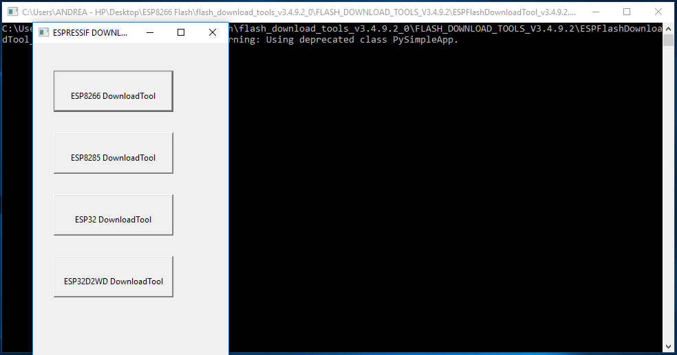
As the time of writing this tutorial these are the latest versions, you can download the new SDK releases and flash tools from their website.Connect the USB-to-Serial converter to a USB port on your PC, and power up the ESP. Start the Flash Download Tool, and you should see the startup screens as shown below. The back window is where a complete activity log for the download tool is recorded. The top window is a tool selection window; because you are working with an ESP8266 module, click the ESP8266 Download Tool button.
![]()
If this is the first time the ESP8266 download tool has been used, a window will open with no data in the form fields. If the SPIDownload tab near the top of the window is not selected, select it now.
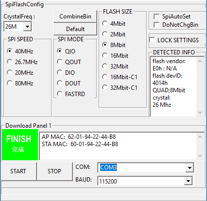
If any of the boxes have check marks in them, uncheck them all. Next, make sure that the COM port you are using and the correct BAUD rate are selected at the bottom right. Click the radio button under SPI SPEED for 40MHz, and the radio button under SPI MODE for QIO. Do not click any other radio buttons, add any check marks, or enter any data.
Connect GPIO 0 of the ESP-01 module to GND for entering the bootloader mode and leave it there for the rest of this tutorial. Now restart the module and press START in the flash tool. The download tool will work for a few seconds to read the contents of the, in my case, ESP-01 module and print the results in the appropriate panels as shown below:
![]()
Here's what has happened during the download tool process time:
- The download tool determined the size of the EEPROM on the module as "QUAD;8Mbit," which translates to 1Megabyte.
- The download tool determined the crystal speed to be 26MHz.
- The download tool read the MAC addresses for your ESP-01 module in both the AP (Access Point) mode and in the STA (Station) mode, and entered them in Download Panel 1. (Note that the MAC addresses for your ESP-01 module will be different from the addresses shown above; record the MAC addresses of your module for future reference.)
Flashing the new firmware:
Finally, you are ready to select and write the new firmware to your module. Set SpiFlashConfig as follows (NOTE your my be different, see the DETECTED INFO panel):
- Select CrystalFreq as 26M (in my case).
- Click the SPI SPEED radio button for 40MHz.
- Click the SPI MODE radio button for QIO.
- Click the FLASH SIZE radio button for 8Mbit (in my case).
Select the binary files to be downloaded from their storage locations as shown in the table below. (The files listed below are contained in the ESP8266 SDK v2.0.0 folder that you dowloaded and stored on your PC, ESP8266 - Flash files > esp8266_nonos_sdk_v2.0.0_16_08_10 > ESP8266_NONOS_SDK > bin).
![]()
NOTE, in this tutorial we are not using the first and last bin file. Your flash adress my be different according to your flash size. For the ESP-01 they are as follow:
...bin\blank.bin 0x7E000
...bin\esp_init_data_default.bin 0x7C000 ( 1 MB module will require this address: 0xFC000)
...bin\boot_v1.6.bin 0x00000...bin\at\512+512\user1.1024.new.2.bin 0x01000
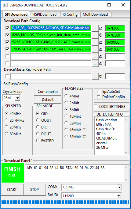
Select all 4 files and their appropriate flash addresses or if you just want to restore the AT firmware select only the v0.9.2.2 AT Firmware file with its appropriate flash address. Make sure that the boxes of these 4 (or 1 for only the AT firmware) files are checked on the Flash tool. After rechecking all the file paths and hexadecimal storage locations click START.
![]()
The download tool will work for several seconds to write the binary files to your ESP module. When the blue progress bar reaches the right side of the window, the flashing process is complete as shown on the picture above.
Disconnect the ESP from your PC, remove GPIO 0 from GND and pull it to VCC or leave it disconnected for normal operation. Open up Serial monitor in Arduino IDE and with the command AT+GMR as before check if you sucesfully updated your firmware.If you have a question or something isn't working feel free to post a comment so I (or someone else) can help you.
Setup & Update the ESP8266 - Getting Started Guide
Update the ESP8266 and connect it to Arduino IDE. A beginner tutorial for later use with Arduino and OpenHAB in my Home Automation series.


Discussions
Become a Hackaday.io Member
Create an account to leave a comment. Already have an account? Log In.
I am working on setting up Mesh network using ESP 8266 module.
I have received the module and was going through the post for setting up the things.
I have a question,
Do I need to explicitly flash the firmware to my new module? or it will have firmware loaded and I can simply start working on interfacing it over UART.... use AT commands and configure the module?
I am confused because there are various posts on the similar lines but they talk about loading the firmware and all... However in my case I am not targeting any change or programming in ESP8266.
I will connect the module with my MCU for configuring it and forming Mesh network.
Are you sure? yes | no