Pepijn de Vos
-
V2 is live on Tindie!
08/22/2018 at 18:54 • 0 commentsAfter a long time, and a completely redesigned case and major changes to the software, it is finally ready!
Check it out: https://www.tindie.com/products/pepijndevos/accessible-guitar-tuner/
-
Case
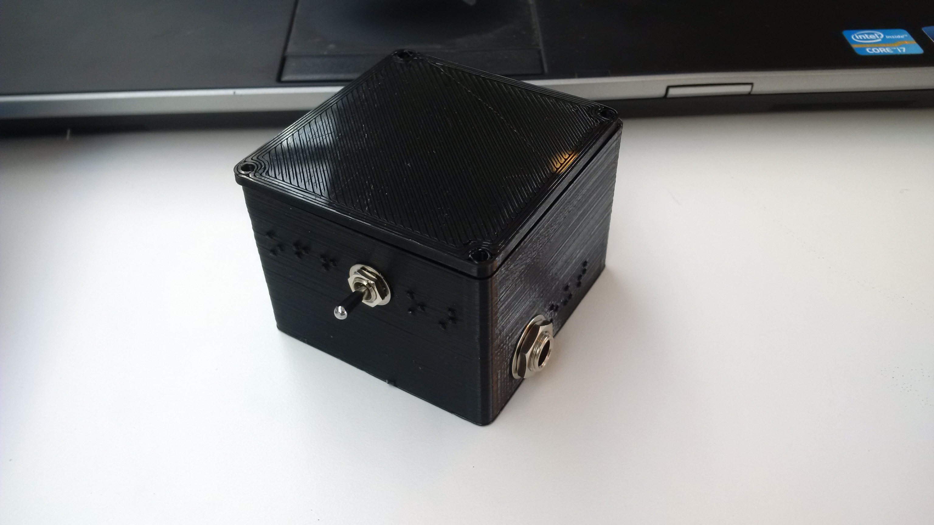
02/27/2018 at 14:52 • 0 comments![]()
A friend helped me design this beautiful 3D printed case for the tuner. It looks really pretty, but there are plenty of problems left to solve:- How do I smooth the texture? (wilt alcohol, I've heard)
- How do I make everything fit? (some holes are still wrong)
- How do I close it? (the screw holes are not good enough now I think)
- How can I make more of them? (University's design lab doesn't allow that)
- How much will it cost?
Especially the last item is a concern. Making a prototype at the university is free, or only for material costs, but on 3D hubs this case seems to cost 20 Euro, easily. That's not viable. Maybe I need to look into laser cutting?
-
Third revision PCB
02/19/2018 at 20:33 • 0 commentsIt's finally here, the third revision! With the help of a few contributors, I now have a working input and a 3D printed case!
They key realisation was that instead of doing this broken automatic gain stuff it would be much simpler to get an ADC with sufficient range for all inputs. This greatly simplified everything. On top of that I also replaced my broken MOSFET output stage with an integrated D-class amplifier chip.
The new PCB pretty much worked right away, so then all what was left to do is improve the software.
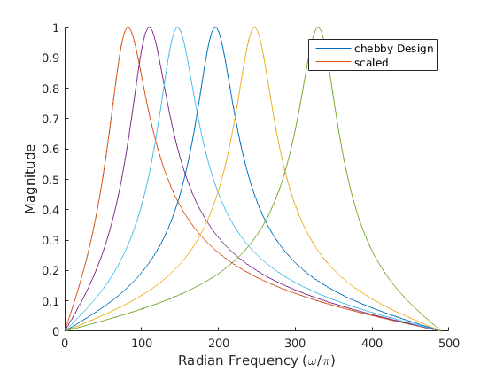
I finally got around to implementing and fixing a second order IIR filter, which I'm using to band-pass the input to reduce noise, and also to low-pass the final signal to the clicker, instead of this scrappy envelope detector I had before.
SO to sum it up, everything is moving in the right direction, and I hope to finish the first batch of 10 boards in the coming weeks and put them on Tindie.
-
A voltage regulator is not a reference
10/08/2017 at 08:39 • 0 commentsBetween exams and studying and surviving, I'm continuing to debug the oscillations in the amplifier circuit, and I think I'm finally on to something. I talked to a friend who works at Prodrive (super nice company) and another friend who was in Green Team Twente (super nice team) with me, to get an understanding of what is going on.
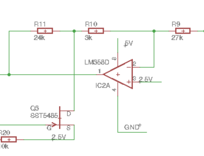
To get an opamp to oscillate, you either have to have positive feedback, or have a phase shift in your negative feedback such that it becomes positive feedback. I did some simulations and thinking, but neither of these seemed the case. The negative feedback is fairly negative, and the positive feedback is directly tied to a voltage regulator.
So my thought was simple: therefore it must be the voltage regulator. So I probed that, and HOLY MOLY.
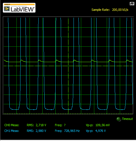
![]() There are peaks of 100mV on the supply, compared to a 10mV input. No wonder... But why?!
There are peaks of 100mV on the supply, compared to a 10mV input. No wonder... But why?!Well, it turns out that most voltage regulators can only source current, not sink current. So when the output is high, some current is flowing through the JFET towards the 2.5V line, causing it to peak. (Or at least that's the thought. In my simulation the current through the JFET is way less than other current draws, so total current should never become negative)
![]()
What I should do for the next revision is to pick a proper voltage reference that can sink current as well. As a stop-gap measure, I attempted to put a 1k pull-down resistor on the LDO to keep it at 2.5V, but this does not seems to have completely solved the problem. I think that means either the current influx is more than 2.5mA, or the LDO is too slow, which both seem unlikely, so maybe I'm still missing something.
-
Too Automatic
09/21/2017 at 17:16 • 0 commentsOver the last few days I've been debugging the input stage. This stage consists of a high-impedance buffer and an automatic gain control stage.
First up, the input buffer. Because piezo elements act like a really tiny capacitance, any input resistance forms an RC filter with the piezo. So in order to have a good frequency response for low notes, an input impedance of many megaohms is needed. A good way to achieve this is to bootstrap the input from the output, so that effectively, no voltage drops over the bias resistor.
However, this means you apply positive feedback, with brings the risk of oscillation. While it seemed to work while I tested the whole circuit, when I tried to measure this particular part, it oscillated all over the place. For now I simply removed the bootstrap circuit so that the impedance is lower, but it's more stable for now.
But now I get to the most complicated circuit on the board: the automatic gain control circuit. At this point, nothing makes sense and everything either works perfectly or oscillates all over the place depending how you look at it and how you hold the probes.
I programmed the AVR to go to sleep, which seemed the reduce the amount of batshit crazy signals I was seeing. This suggests to me that the isolation between the analogue and digital circuit is not good enough. But this does not explain all of it, as I'm still seeing some things I can't explain.
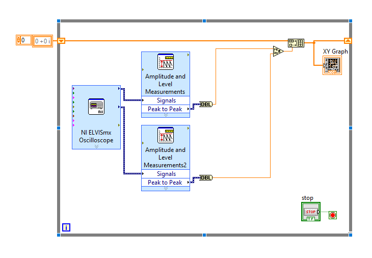
My original plan was to make an XY plot of the amplitude of the input versus the output, so I could see how the gain was being controlled.
![]()
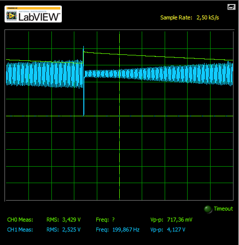
The resulting plot made no sense, so I did some more debugging. When I finally zoomed out far enough to notice, I was quite startled.
![]()
What you see here is that the peak detection capacitor discharges slowly, increasing the gain until it hits the turn-on point on the JFET, causing it to peak, completely charge the capacitor, and slowly discharge again.
Maybe I should tweak the turn-on point, maybe I should tweak the gain on the JFET, maybe I should add a charging resistor so the peak detector increases more gradually, maybe I should not use feedback but only feedforward to avoid any stability concerns, or maybe I should ditch the entire AGC stage and come up with something better.
It suffices to say that making a guitar tuner is not that hard, making a usable product is a monumental challenge.
-
Finalist!
09/19/2017 at 08:06 • 0 commentsI found out my project is one of the finalists in the accessible technology Hackaday Prize! I'm super thrilled about this.
I should mention that the current version of the tuner does not use FFT at all. The comments mentioned a beat frequency oscillator and strobe tuner, which is a pretty good description how my tuner actually works.
Meanwhile progress has been a bit slow since university started again. I started to write new software that uses a lower sampling frequency and signed integers so I could filter the input signal to get rid of uninteresting frequencies to make tuning more robust. This does not work at all yet though.
![]()
Instead I patched up the current software to run on the new PCB revision, and that still works at least as well as the previous version. When I have the time I intend to write some Labview code to profile my AGC stage, so I can tune its range to be more practical.
As for the problem of the piezzo/humbucker, I decided I should just focus on the piezzo for now, and possibly sell a separate version for electric. That would just be a matter of changing a few resistors.
One thing I'm still considering is using a integrated VCG circuit. I found one that has a 27dB range, which would almost do the trick, but the simulation model is broken, so i don't have faith in designing a circuit with this chip. -
Signal levels
09/10/2017 at 07:53 • 0 commentsThe good news is that all the parts of the PCB worked more or less on the first try. I could program the AVR, read the encoder, output sound, and record sound input.
The bad news is that none of them work as well as they should.
I replaced then expensive power opamp output with a D-class mosfet stage and a filter. At first it did not really work because the gate capacitance of the output fets was too big for my 10k pull-up at 60KHz. Once I put a 1k resistor there, it more or less worked, but the output filter is completely inadequate, leading to lots of switching noise on the output. It also draws a lot of power it seems.
But the biggest issue is the input stage. I completely redesigned that to accommodate and normalise different input levels, which was quite a challenge. To my relief this part also worked on the first try, but for signal levels from 10-100mV.
The microphone clips output more like 1mV. It seems every time I measure the clip microphones, their output is reduced by a factor of ten.
I remember when I started this project, I took an electric and an acoustic guitar, and measured their output to be in the 100mV range. So I figured I could design one product that works with both.
For the first revision of the PCB I discovered that different clip microphones have very different signal levels. I'm doubting my own memory now, but I'm absolutely sure one microphone had much higher output than the other, and quite a bit lower than the electric guitar.
So I designed the second PCB revision with automatic gain control that would work all the way from the 10mV I remember getting from the microphone, up to the 100mV I remember getting from the electric guitar.
Except, now I'm only getting 1mV from both microphones, and according to Wikipedia, some electric guitars go up to 1V! That means if I want to support both types of input, my gain has to adjust by a factor of a thousand, rather than ten.
So things are looking a bit grim here. I'm not sure where to go from here, and I'm really doubting myself now.
-
New PCB
08/31/2017 at 14:48 • 0 commentsAfter a lot of struggles with JFETs and opamps, I finally managed to design a circuit that (at last in simulation) achieves acceptable gain control. I hope that I can compensate for the rest in software.
I ordered the PCB, but since I was going on holiday, I ordered from China this time. I've been told that my parents received some mysterious green plates, so I hope to continue as soon as I get home. Although university also starts a few days later.
-
PCB!
08/31/2017 at 14:44 • 0 commentsI designed and ordered the PCB.
This went fairly smooth, I made a few mistakes that I had to fix with some creative wiring, but I had two major problems:
I'm having trouble finding the right case. I bought one that almost fit, but left no space for giant 1/4" plugs.
After testing with several real guitars and microphones I found that voltage levels vary a lot from microphone to microphone, To fix this, I had to redesign the whole input stage to have automatic gain control.
-
PIC or AVR?
08/31/2017 at 14:40 • 0 commentsIn the original FFT based project, I was very much resource constrained. I read PIC has some nice DSP features, so my original plan was to use a dsPIC.
However, sampling from Microchip took way too long, so by the time they arrived I had already started with an Atmega328. Due to the new algorithm this turned out to be okay.
I also learned later that PIC does 2 cycles per instructions, so the 40MHz is about the same as 20MHz AVR.
I transferred the breadboard circuit to stripboard, and did more testing. This seemed promising, so I proceeded with designing the PCB.
Accesible Guitar Tuner
A guitar tuner with audio feedback for bind guitarists
 There are peaks of 100mV on the supply, compared to a 10mV input. No wonder... But why?!