Close
0%
0%

Isolated ST-Link v2 with power output

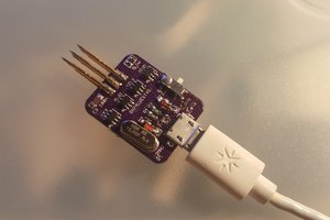
A custom isolated ST-Link v2, with optional isolated 5v or 3v3 output to power circuit whilst programming/debugging.

Similar projects worth following
Whilst developing AC powered projects, I encountered two issues:
1. An isolated ST-Link was needed, since my projects were not referenced to earth.
2. The ST-Link needed to power the microcontroller when programming it.

The two methods used till now to circumvent this issue:
1. Use a laptop and disconnect the power cable, hence removing the earth reference.
2. Modify a normal ST-Link with diodes to power the microcontroller.

I thought it would be worthwhile to develop an isolated ST-Link programmer for both STM8/STM32 microcontrollers, that had an option to provide the 5v/3.3v required just in case.

Instead of re-inventing the wheel, I had a look online and the schematics for DIY ST-Link boards were readily available, I have linked the two websites I referred to when designing this project. All that remained was to design in the isololation, and the power output selector.

I will be posting the full project here, and updates as everything progresses. You should be able to get a step-by-step instruction as to how to build this module and work it, as well as all the files you need.

ISO_STLINK_BASIC.dch

Diptrace Schematic

dch - 273.71 kB - 08/21/2017 at 19:38

Download

ISO_STLINK_BASIC.dip

Diptrace PCB

dip - 255.80 kB - 08/21/2017 at 19:38

Download

ISO STLINK BASIC - Schematic.pdf

Schematic pdf

Adobe Portable Document Format - 53.31 kB - 08/21/2017 at 19:38

Preview

Gerber.zip

Gerber / NC drill files

x-zip-compressed - 21.07 kB - 08/21/2017 at 19:38

Download

firmware.bin

octet-stream - 64.00 kB - 08/19/2017 at 20:50

Download

View all 7 files

  • 1 × C1 - 10uF, 0603, 6.3V Capacitors
  • 1 × C2 - 4.7uF, 0603, 6.3V Capacitors
  • 4 × C3,5,9,11 - 1uF, 0603, 6.3V Capacitors
  • 7 × C4,7,8,10,13,14,15 - 0.1uF, 0603, 6.3V Capacitors
  • 2 × C6,12 - 18pF, 0603, 6.3V Capacitors

View all 31 components

  • Boards have arrived!!

    Dr. Kaz08/19/2017 at 20:43 0 comments

    The boards and components all arrived, so today I sat to solder everything and test the module. Whilst soldering the components on, I realized I had gotten the pattern wrong for the 

    After soldering all the components on, I used the ST-Link part of a STM32 discovery board I own to flash an old version of the ST-Link V2 firmware onto the board using the 

    However, after the microcontroller was flashed, only the red LED was blinking at around 0.5Hz, and the unit was not connecting to the PC.

    After around 4 hours of debugging, it turns out I had forgotten two things:

    1. I had left the VBAT pin floating - the datasheet says that if no external battery is used, it is recommended to connect this to VCC.

    2. I hadn't provided a pull-up on the USB D+ line. 

    Trawling through the components I had at home, I found some 3K6 resistors, and soldered one as a pull up for the D+ pin, and hey presto, the unit was recognised as an ST-Link device on the PC.

    Then I went back to the ST-Link utility and tried to update the unit to the latest ST-Link v2 software, and it worked!!

    Leaving the VBAT pin unconnected wasn't such a major issue for me, and the unit worked without connecting it to VCC.

    I'll modify the documents with these changes, and provide a step by step, really chuffed that it all worked.

  • First set of ordering done...

    Dr. Kaz08/08/2017 at 21:16 0 comments

    So the schematic, PCB, and case has been designed, and here are the costs:

    1. Components - £12.835 from RS & Farnell 

    2. PCB - £0.730 including shipping for a single board (£7.3 for 10)

    3. Case - £5.96 for both halves printed in ABS, with 0.2mm layer height.

    The PCB has been ordered, and the case is being printed, components will probably be bought once the PCBs arrive, as they only take a day.

View all 2 project logs

  • 1
    Ordering

    Download the gerbers, and order from your favorite fab house. The board is double sided, plated through hole, silk screen on one side only. The board size is 50mmx40.62mm, with the minimum track/gap being 8mil.

  • 2
    Soldering

    Once the boards arrive, solder all the components onto the board. My personal method is to go according to height, starting with the smallest, however it is also good to check whether any pad will be difficult to get to if another component is soldered on first.

  • 3
    Firmware

    Download the ST Link Utility from here, and download the firmware file from the project files list.

    Connect the J3 pins to either another ST-Link, or the ST-Link part of a discovery board. There are also ways to flash the firmware using other dev boards, and USB-UART modules, however I won't go into that here, there is ample info already out there.

    Connect the mini usb of both the ST-Link, and this module to the PC.

    On the ST-Link Utility software, open the downloaded firmware file. Then click Target, and Program/Verify.

    Once the flashing is complete, disconnect both the mini usb cables.

    Disconnect the programming wires.

    Connect the mini usb to the PC. The module should come up as an ST-Link v2.

    Then on the ST-Link Utility software, click ST-LINK, and click Firmware Update.  The version will appear, and also the software will show the latest version available. Click Yes.

    After its completed flashing the latest version, congratulations, you now have an isolated ST-Link v2!!

View all 3 instructions

Enjoy this project?

Share

Discussions

Nima Askari ----- نیما عسکری wrote 06/11/2020 at 11:12 point

i create it . But does not work . I only connect to mcu in 100khz . But can not program

  Are you sure? yes | no

Similar Projects

Does this project spark your interest?

Become a member to follow this project and never miss any updates