-
Wireless Sensor Test
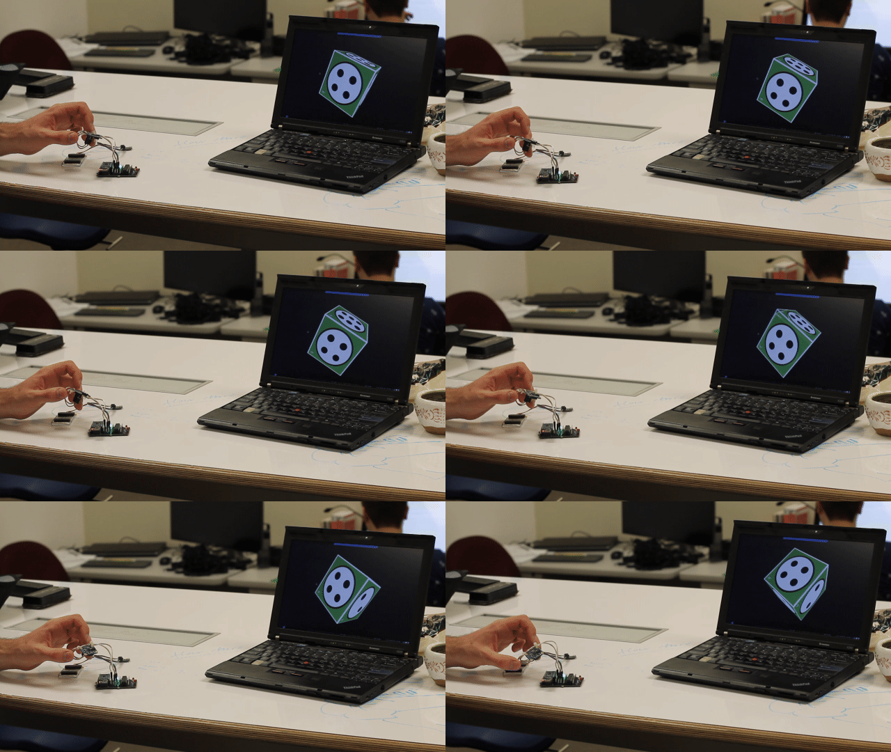
08/27/2017 at 17:22 • 0 commentsIt works! Quaternions are gathered from the BNO and sent back to a desktop application:
![]()
Now the real work begins:
- Need a second one!
- I'm sharing this one with a local college, having two means myself and that group can work without stepping on toes.
- Need to hook up more BNO055s and test with all of them being polled.
- At least 3 initially for thumb, index, and middle fingers.
- Write real desktop software to do user testing, not this repurposed Qt example stuff.
- I need to learn more about the math involved. You can see in the gif that the rotations are being applied backwards.
- Start work on the next PCB version!
- Will use surface mount components!
I've handed off the functioning PCB to H2I (Human Interfaces Innovation Lab) where they'll begin working to integrate it into gesture recognition tools.
- Need a second one!
-
Troubleshooting the First PCB
08/27/2017 at 14:45 • 0 commentsBack dated August 10th 2017
So there are some bugs with the first assembled PCB. I'm glad now for the decision to make the PCB design as close to the breadboarded prototype as possible, because we have a reference to work with.
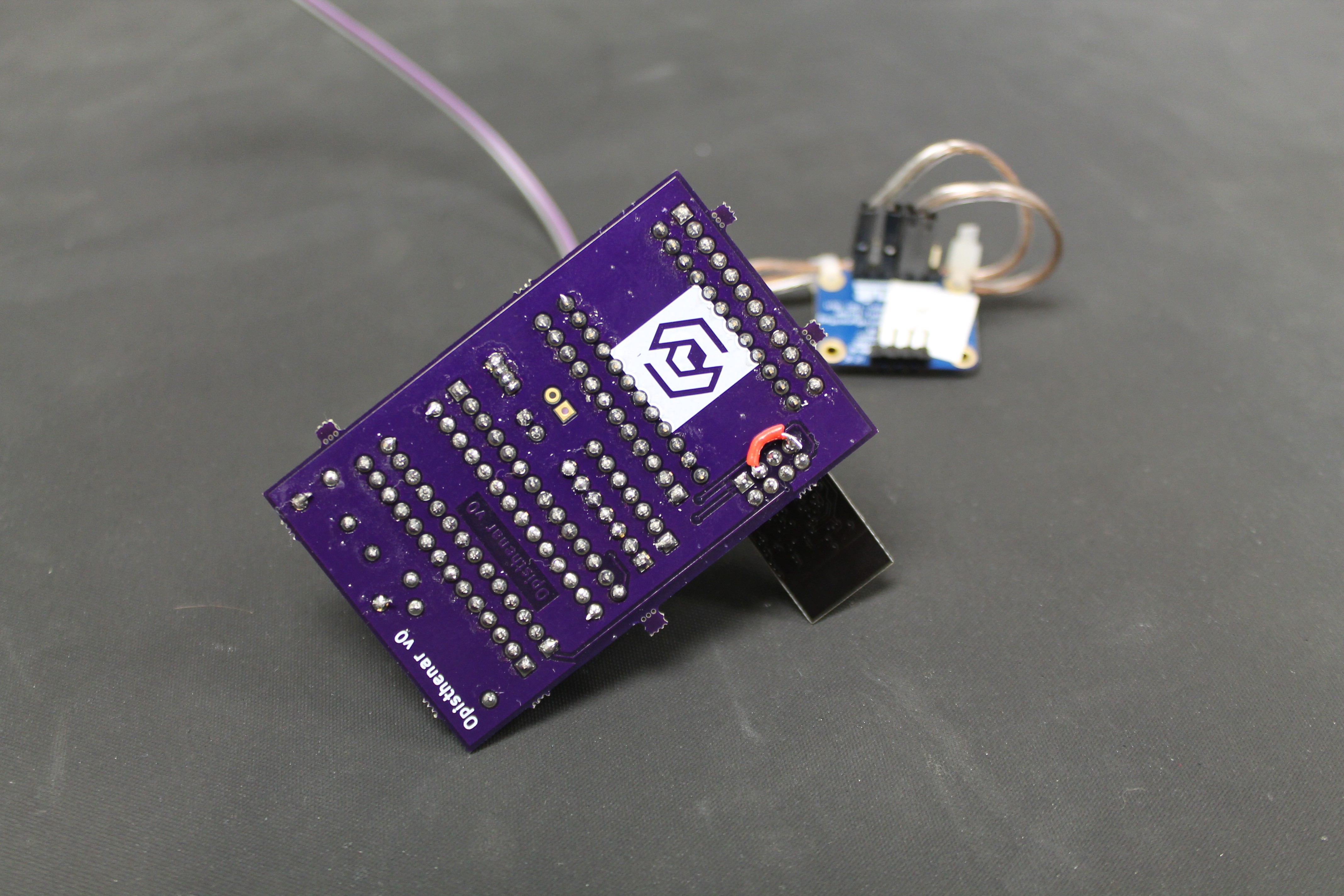
It turns out I left a connection off of the ESP pins: CH_PD was left disconnected and needs to be pulled to Vcc for the ESP to work the way we want it. A small wire soldered in fixes that:
But now that we can see the microcontroller serial output from the ESP, the ATmega boot loop is still there :-/
Again it was pretty fast to find the issue: The PCB has a new ESP8266 on it, with stock esp-link firmware, the GPIO pin that controls our ATmega's reset line wasn't configured, and so it was creating spurious resets. With that config change, the resets stopped and we could finally start testing wireless transmit!
-
PCBs Arrive
08/24/2017 at 04:37 • 0 commentsBack dated July 24th 2017
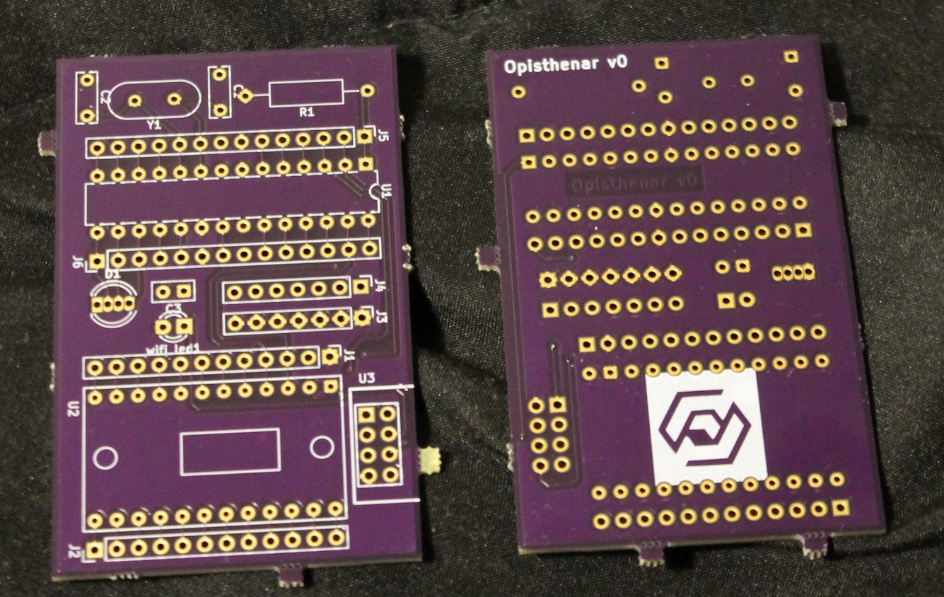
The OSHPark PCBs:
Assembled:
Testing it fails, as the ESP's AP doesn't show up and the ATmega is stuck in a boot-loop.
-
Designing a Prototype PCB
08/23/2017 at 12:57 • 0 commentsBack dated July 12th 2017
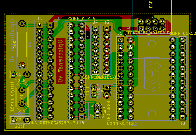
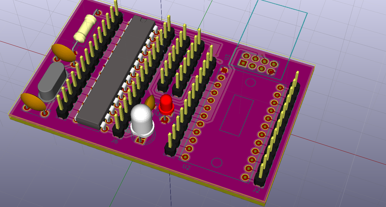
The proposed PCB design:
![]()
![]()
Once the breadboarded proof of concept was working, it was time to learn how to use KiCad. I'd never (successfully) designed a PCB layout before, so there was a lot of tutorials to read through and examples to follow before tackling this board.
I named the PCB Opisthenar, which supposedly means "the back of the hand" in medical terminology; the current implementation includes strapping this board to the back of the tracking glove. The design was meant to be 1:1 against the breadboarded precursor to keep the layout simple (for my sake) and to avoid introducing unexpected bugs so we could go back and take a more narrow troubleshooting path for problems.
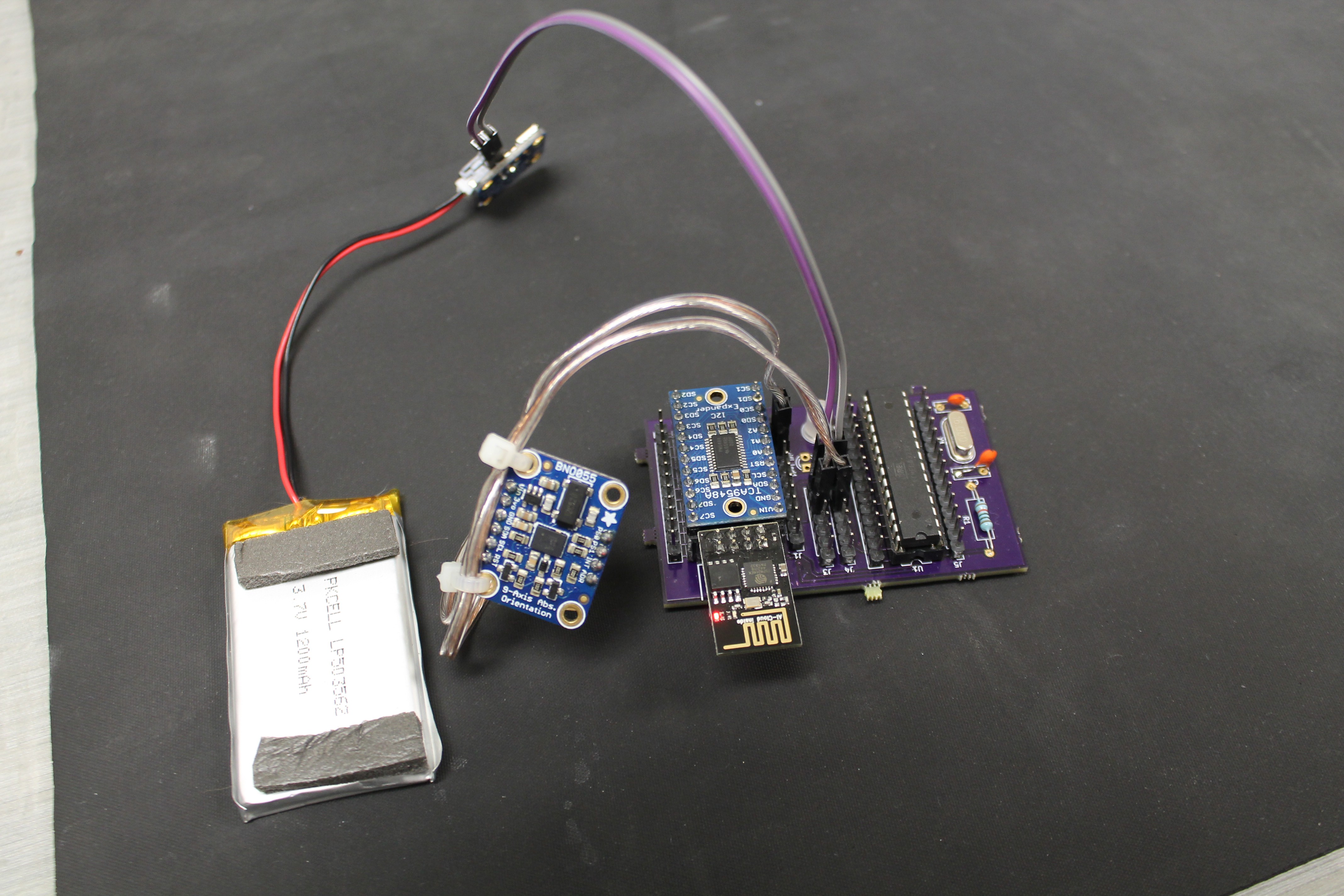
Now that we have a nicer image of the circuit to look at, let's walk through the design. At the heart is an ATmega328P, which was fast to implement because I'm familiar with avr-libc, but will one day likely be absorbed by the ESP8266, which has a lot of leftover horsepower. The ATmega is connected to an I2C mux, and through the mux to the BNO055 orientation sensors. RX and TX on the ATmega goes to an ESP-01 which is running esp-link to make the serial connection wireless. And that's really about it, the design is simple and hopefully easy to implement for others to take and build cool projects on!
-
Breadboard prototype
08/11/2017 at 03:21 • 0 commentsBack dated June 30th 2017
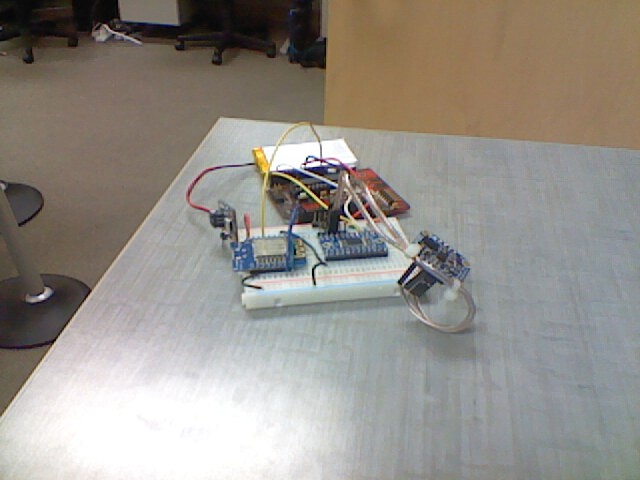
The first wireless setup:
![]()
This is from back when I worked as a research assistant. We were investigating open source and accurate ways to get gesture input to a computer after seeing how simultaneously expensive and lacking commercial systems could be. One of the approaches was to try our hand at producing an open source gesture tracking system in-house, which I've forked to become Gestum after parting ways with the lab.
A lot of time was spent chasing full 3D tracking with IMUs. It just didn't have a prayer with current consumer hardware. Once we'd shifted focus to orientation/rotation based tracking things started to move a little faster. The image above is of a BNO055 IMU reporting rotations to an ATmega, which then sends them over an ESP8266 with telnet back to a desktop.
 Christopher