-
Creating the case
08/23/2014 at 10:56 • 0 commentsRight now i try to crreate a case thats stylish and also cheap to print on shapeways for example.
I will add later more information...
-
Creating a 3D model
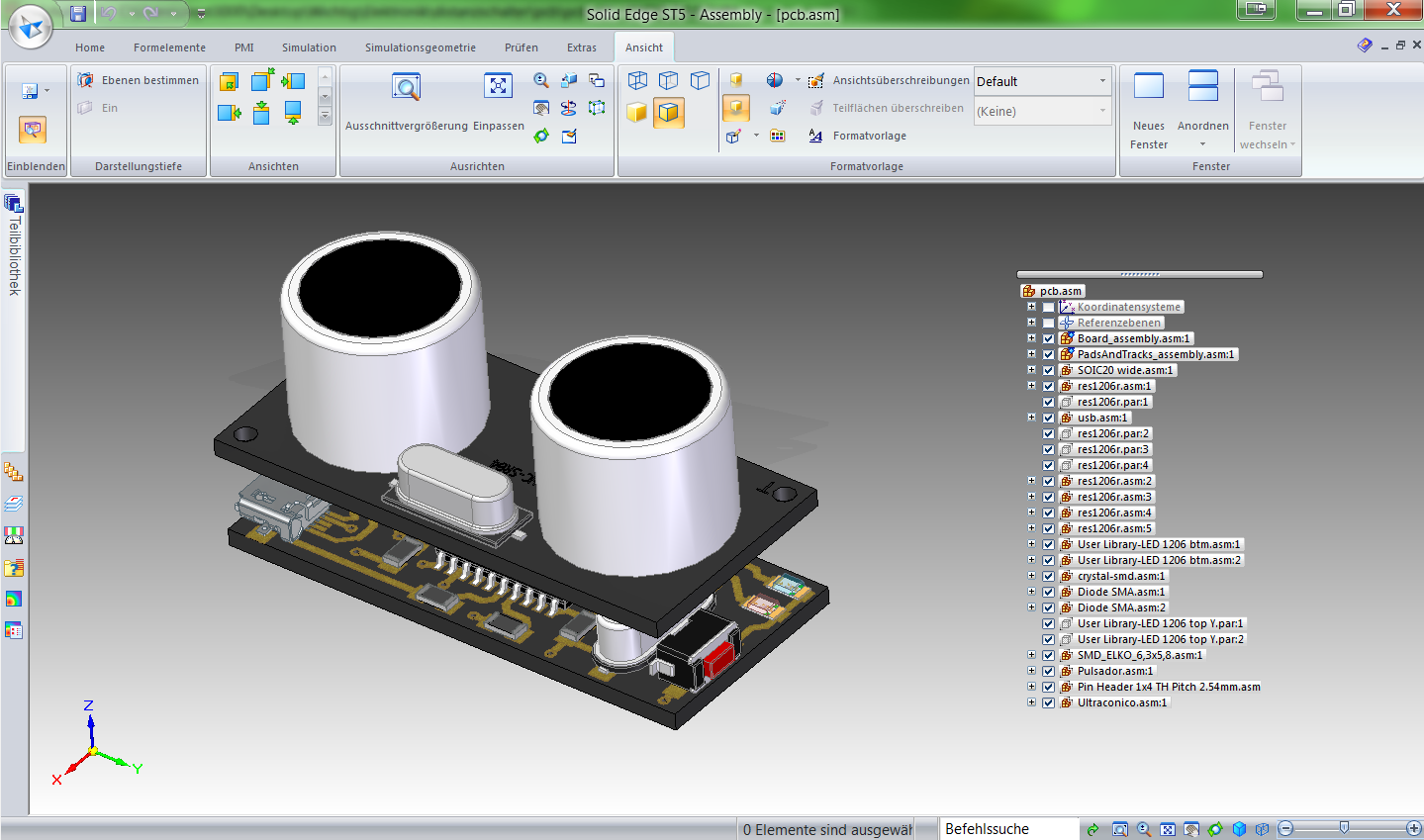
08/23/2014 at 10:54 • 0 commentsThe next step is to create a 3D printed case for the PCB and the sensor. But to do this i first created a 3D model of the hole assambly to thest everything first. And as it turns out it really was a good idea:
![]()
As you can see i forgot the mounting holes in the PCB...
For the 3D software i use SolidEdge as i learnd how to use it in shool and is aviable for free for students.
-
Creating a cuirit diagramm
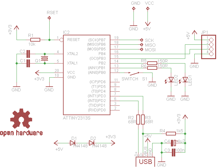
08/23/2014 at 10:50 • 0 commentsOfcourse i have to publish the cuirit diagramm so others can easily build their own Ultrasonic switch:
![]()
-
Laying out the PCB
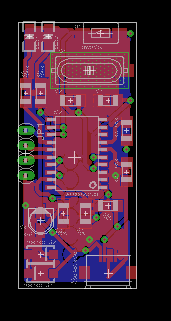
08/23/2014 at 10:48 • 0 commentsat the moment im working on the layout for the pcb. I decided to use smd components as you can see in this picture:
![]()
With these smd components i can get the hole thing fit below the HC-SR04 sensor. But still i need a double sided PCB, and ony have exposed pads as programming port...
But on the otherhand beacause the PCB is that small it will be very cheap to manufacture in china :)
Ultrasonic Music Control
A small, driverless device that allows you to control your music with the wave of a hand.
 Lloyd3000

