 sayanee
-
1Build the PCB
Note: Do not connect the batteries yet!
- Download the KiCad files
- Generate the GERBER files or download them
- Manufacture the PCB
- Order the Bill of Materials
- Solder the parts on the PCB
- Do a continuity test
- Use the test firmware to ensure everything is working
- Short the 2 header pins on
P4for boot mode - Connect an FTDI chip to
P3 - Connect the other end of the FTDI chip to the laptop via USB
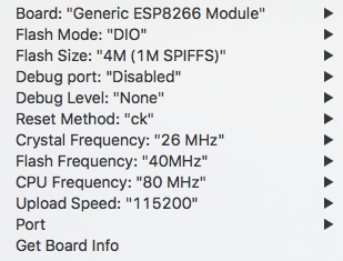
- Open Arduino IDE with the following configuration
![]()
- Upload the test firmware
- See the test results on the Serial Monitor
- Short the 2 header pins on
-
2Flash the firmware
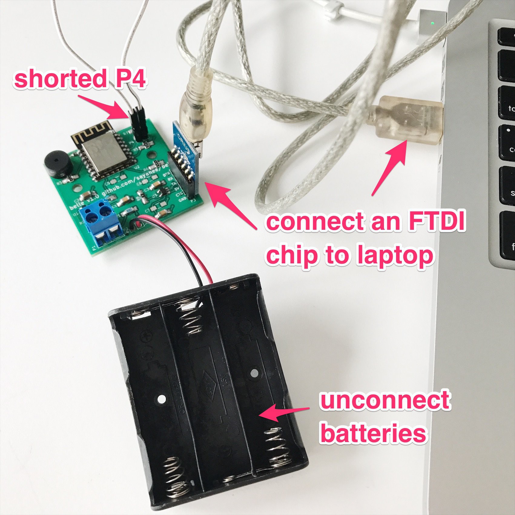
- Ensure the batteries are not connected yet!
- Short the 2 header pins on
P4for boot mode
- Connect an FTDI chip to
P3
- Connect the other end of the FTDI chip to the laptop via USB
![]()
Open Arduino IDE with the following configuration
![]()
Flash the final firmware to the board. Try out other firmwares too!
Remove the FTDI chip and the remove the shorted header pins of
P4
-
3Configure in IFTTT
- Configure IFTTT with Webhooks and Notification channels to Receive a web request
- Put the event name as
bell_pressed![]()
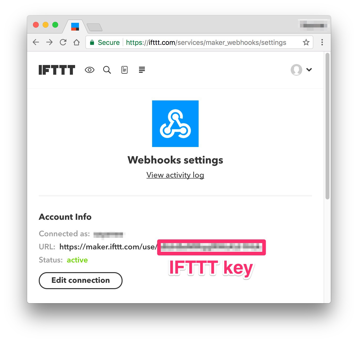
- Download the IFTTT app on mobile as well
- Note the IFTTT key on the maker_webhooks settings page
![]()
- Configure IFTTT with Webhooks and Notification channels to Receive a web request
-
4Connect to the actual door bell
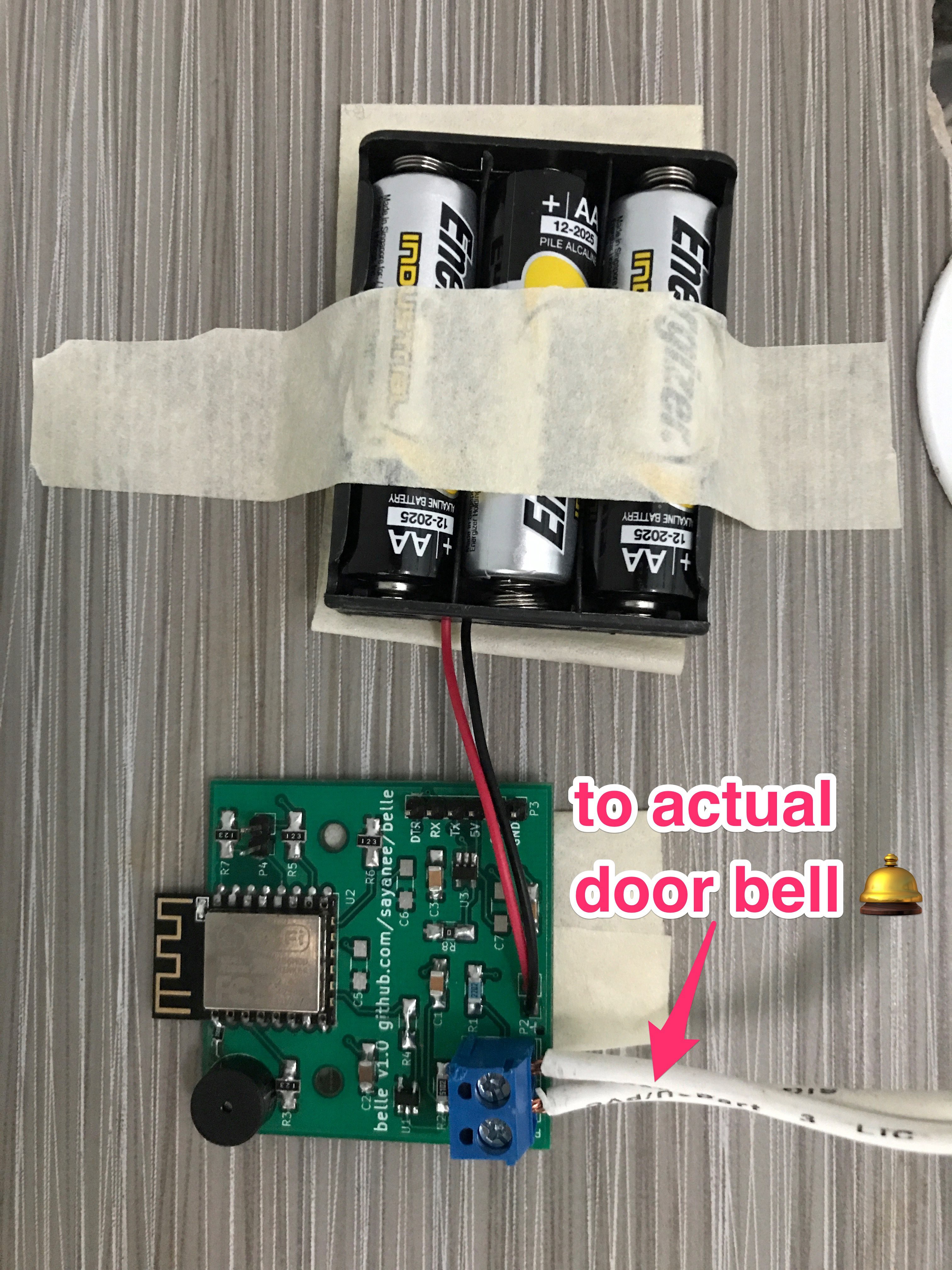
- Connect 3 AA batteries
- Ensure the blue on-board LED is blinking fast
- Connect your actual door bell to
P2connectors
- Mount it up on the wall
![]()
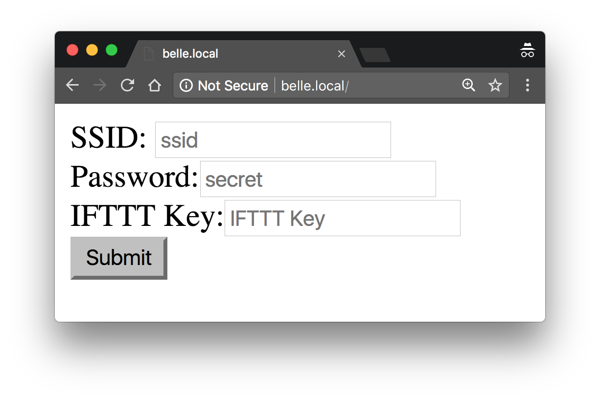
- Connect to WiFi access point with SSID
Belle XXXXand passwordbeautyandthebeaston mobile / laptop
- Visit page http://belle.local
- Fill in
SSID,PasswordandIFTTT Key<br>![]()
Wait for the LED to stop blinking while it connect to the WiFi and then sleep
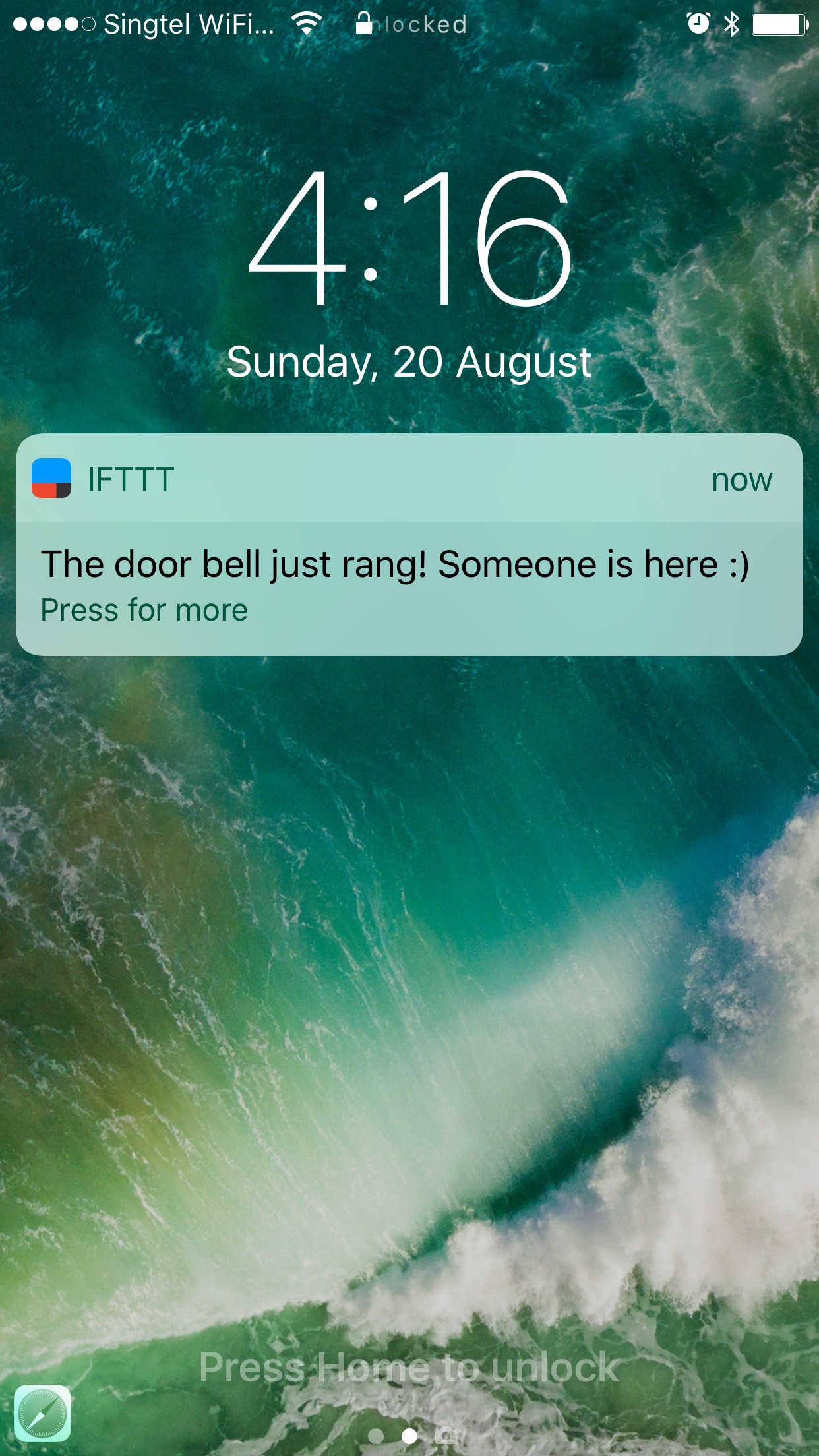
- Press the door bell
You should hear the buzzer and get a mobile IFTTT notification as well :)
![]()
- Connect 3 AA batteries
Belle: Door bell alert with ESP8266 + IFTTT
Get an IFTTT mobile notification when someone presses your door bell

Discussions
Become a Hackaday.io Member
Create an account to leave a comment. Already have an account? Log In.
Cool project! When you say "connect your actual doorbell," what kind of doorbell is it, a standard AC one? Is this just putting your module in the middle of one of the wires going to the button from transformer/chime box?
I'm working on a doorbell project and figured I'd need an ACS712 current sensor since it's for a standard (North American) 10 VAC doorbell (with an unlighted button). That's based on research, being pretty green with hardware, so just curious if you're doing the same setup or something different. Thanks!
Are you sure? yes | no