0%
0%
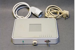
ATX Power Supply Monitor
Inline ATX Power Supply Current Monitoring Board
 Dave's Dev Lab
Become a Hackaday.io member
Already have an account? Log in.
Just one more thing
To make the experience fit your profile, pick a username and tell us what interests you.
Pick an awesome username
hackaday.io/
Your profile's URL: hackaday.io/username. Max 25 alphanumeric characters.
Pick a few interests
Projects that share your interests
People that share your interests


 carbono.silício
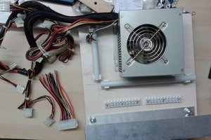
 Christoph
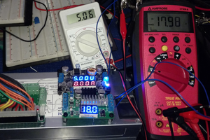
 Ethan Waldo
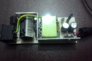
 Sudarshan patil
I can't take a look at the schematic, don't have Eagle. Do you really use those thin wires to carry current to the meters' current sensors, or are the current sensors themselves on the red PCB and the meters are modded to use the external sensors?