Nick Ames
-
On Pause
09/22/2014 at 22:16 • 2 commentsI'm putting the NoteOn project on pause for a bit. Developing NoteOn's firmware has been more tedious than I expected, and I've lost interest in the project as a result. I'll probably start working on NoteOn again 6-12 months from now. In the meantime, feel free to use or adapt it however you like. The design files are licensed CCv4-BY-SA and are available here. The firmware is licensed GNU GPLv3 and is available on GitHub.
I won't be proceeding further in the HaD Prize. Thanks to Hackaday and Supply Frame for putting it on, and good luck to everyone still in the running.
-
Current Status
09/07/2014 at 22:15 • 2 comments(Apologies for the lack of updates; some family stuff has prevented me from working on NoteOn for the last few weeks.)
As of 2014-09-07, the IMU driver (which fetches data from the IMU and aux. accelerometer) has been completed, and prototype 2's defective aux. accelerometer has been replaced.
Auxiliary Accelerometer Replacement Process
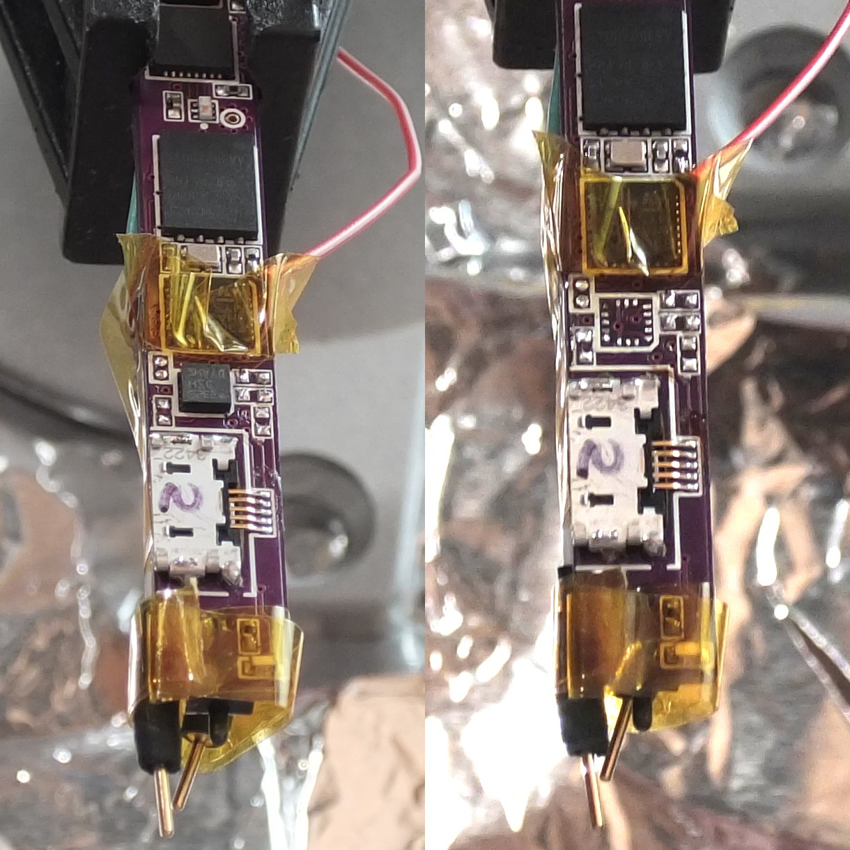
I started out by removing the passive components surrounding the defective aux. accelerometer using a soldering iron, in order to give myself more room to work. (402-sized components can be easily removed by wiping them away with a large blob of solder.) I applied Kapton tape to the adjacent microcontroller to shield it from the hot air, and bundled the SPI debugging wires underneath the board to keep them from melting.
I used an Aoyue 850++ hot-air rework station to remove the defective device, then used an iron and solder wick to remove excess solder from the pads.
![]()
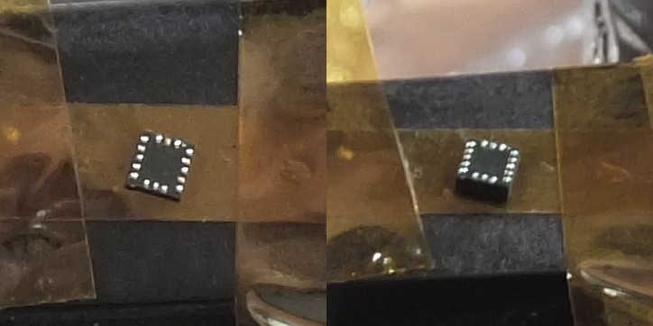
I decided to pre-tin the pads on the new device with solder balls, rather than using solder paste. The only solder paste I have is lead-free, which requires higher temperatures. I stuck the device upside-down on a piece of Kapton tape, applied copious liquid flux, and ran a molten solder blob over the pads.
![]()
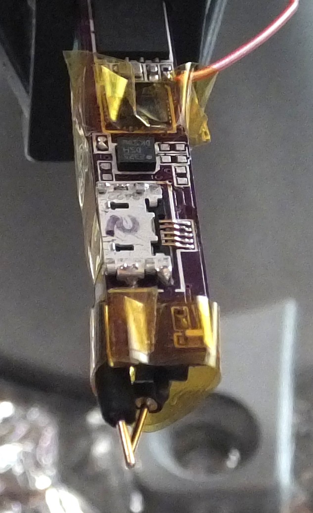
Before attaching the new device, I pre-heated the PCB for about ten seconds with a medium air flow. I then applied flux, aligned the device with tweezers, and heated it for 25 seconds with a low air flow. (A higher air flow is much more effective at heating, but it can also blow the chip right off the board.)
![]()
After replacing the passive components I removed earlier, the new aux. accelerometer responded over I2C and produced valid data.
-
Current Status
08/21/2014 at 04:50 • 0 commentsAs of 2014-08-20, the electrical and mechanical design of the NoteOn prototype is complete. One case and two PCBs have been manufactured.
The first PCB, prototype 1, was damaged by a static shock which disabled its crystal oscillator, so I've been using prototype 2 for development. Unfortuneatly, prototype 2's auxilliary accelerometer doesn't work. (It responds over I2C, but the acceleration readings are always pegged to their maximum value. Checking against prototype 1's working aux. accel shows that the software is not at fault.) I've purchased a replacement accelerometer, and will swap it in once I can aquire a hot air rework tool. All other parts of prototype 2 appear to work fine.
Development on the device firmware is ongoing. The board has been brought up, and I've written drivers for all nessecary internal peripherals, excluding USB. Drivers for the battery monitor IC and external flash memory have been written and tested. I'm currently working on a streaming driver for the IMU. (The driver will stream data continuously from the IMU, with the IMU caching its data in its internal FIFO between reads.) After that's done, I plan on getting Bluetooth communication working.
-
Thoughts on ARM vs. AVR
08/21/2014 at 04:42 • 0 commentsUntil now, I've only used AVR microcontrollers. Although not very powerful, they have good documentation and a high-quality toolchain. (Avr-libc is fantastic.) As NoteOn will require some heavy number crunching (for a microcontroller), I equipped it with an STM32F302, which contains an ARM Cortex-M4 with a floating-point coprocessor.
Setting up a toolchain was difficult. After trial and error, I settled on gcc-arm-embedded for the compiler and utilities with libopencm3 for chip support. (Using ST's library wasn't an option. It comes with a restrictive license which would have prevented NoteOn from meeting the Hackaday Prize openness requirement.) I patched stm32flash to support the F302 in order to download code via the serial bootloader. (Dfu-util may work for downloading code over USB, but I haven't tried it.)
After getting the toolchain working, I found development much harder than with AVRs. The chip is more complicated, but the real issue is libopencm3's lack of documentation. (ST's terse datasheets don't help.) For the most part, the only documentation is the source code.
However, the sweet nectar of DMA, 32-bit word size, and the NVIC (interrupt controller) soothe the pain of development. While AVRs will still be my first choice for small projects, I won't hesitate to use an ARM if the chip is doing any heavy lifting.
-
Machining the NoteOn Case
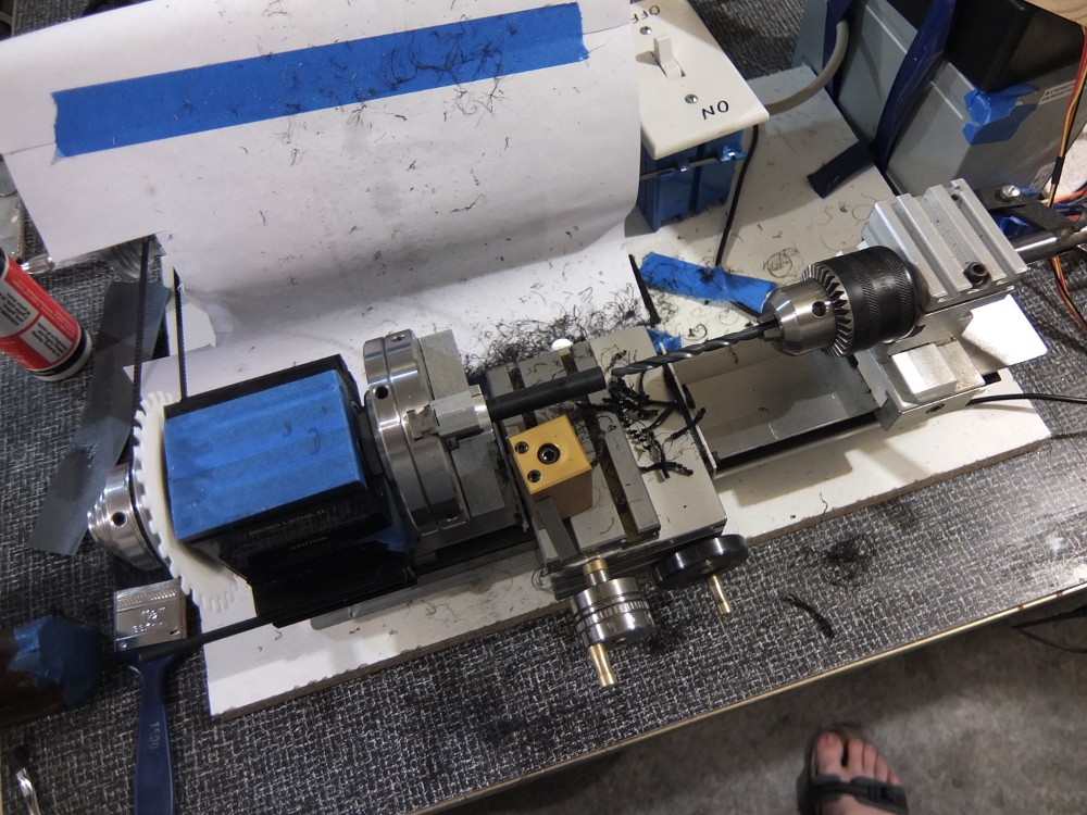
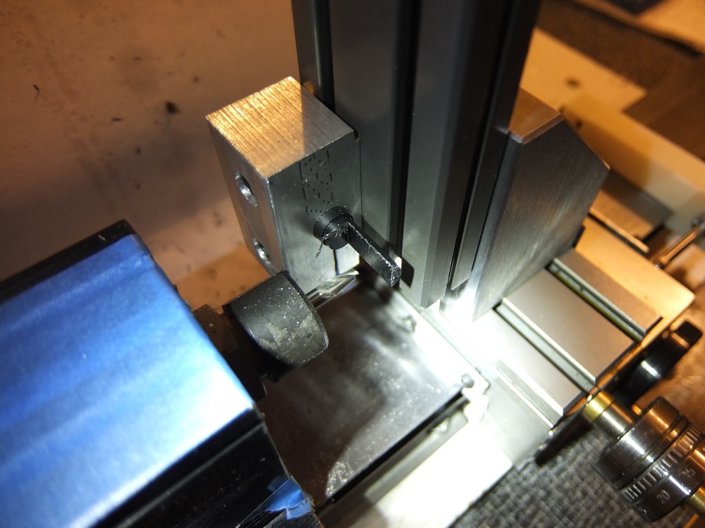
08/21/2014 at 04:08 • 0 commentsI use my Makerbot Thing-o-matic to create most of my project enclosures. It's simple, easy, and inexpensive. For the NoteOn case, this wasn't an option. Most of the parts have thin walls and require a precise fit. Instead, I machined the parts on my Taig Lathe.
The parts were made of black polycarbonate, delrin (for the ink cartridge sleeve) and clear acrylic (for the button/status indicator).
![]()
Most of the parts are tube-shaped. They just need to be turned to size on the outer diameter and drilled. A tip on drilling large holes in polycarbonate: don't use a pilot drill. I don't know why, but a pilot hole causes the larger drill to bind horribly. Also, don't be too aggressive, or the plastic will melt.
![]()
For the PCB shelf, USB slot, and tip switch wire holes, I used my milling attachment with a simple fixture. The fixture is just a 10mm hole with a slot in it that clamps on the OD of the parts.
To get a matte finish on the outside of the pen, I used 380 and 500 grit sandpaper with cutting oil (Cool Tool II). Some hot water and ivory soap afterwards leaves the parts nice and clean.
-
Leadless Packages: Less Difficult Than They Seem
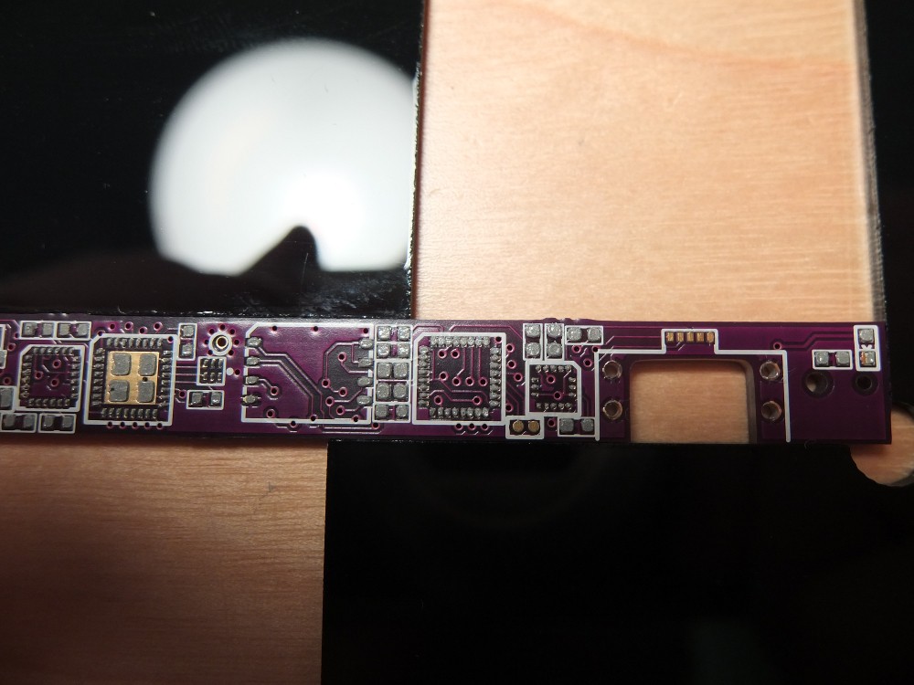
08/21/2014 at 03:50 • 0 commentsSpace is at a premium on the NoteOn PCB. The PCB is only 8.1mm wide, just barely larger than a SOIC package. To make the design fit, I used leadless packages for all the ICs. Most of the chips are QFP or LGA packages. The voltage regulator and battery monitor are chip-scale BGAs.
This was the first time I've used leadless packages on a project, and I was worried that there would be problems with short circuits and dry joints underneath the chips. To my surprise, everything went fine. In this build log, I'll go over the process I used.
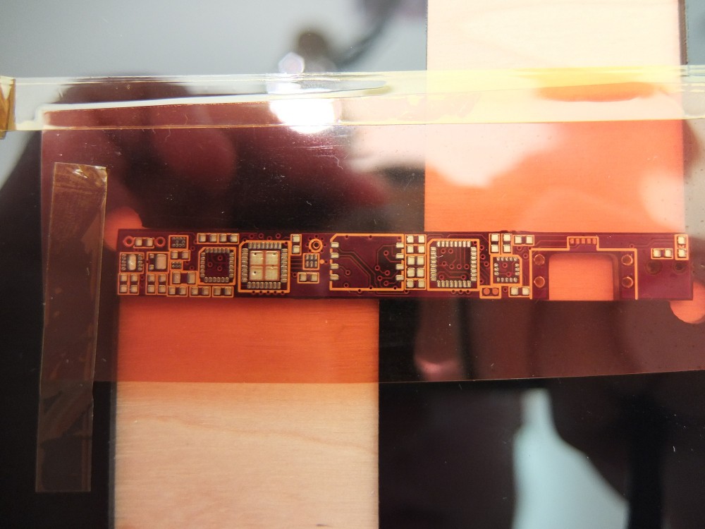
My PCBs were purchased from OSHPark. They produce high-quality boards, and their $5/sq. in. price is a fantastic value if your designs are small. .003" Kapton solder paste stencils were ordered from OSHStencils. I purchased a set of their board guides to rest the stencil on.
![]()
The boards were stenciled with ChipQuik SMD291SNL lead-free solder paste. I had some issues with paste bridging between pads, so I used a needle to scrape the paste out of the way.
![]()
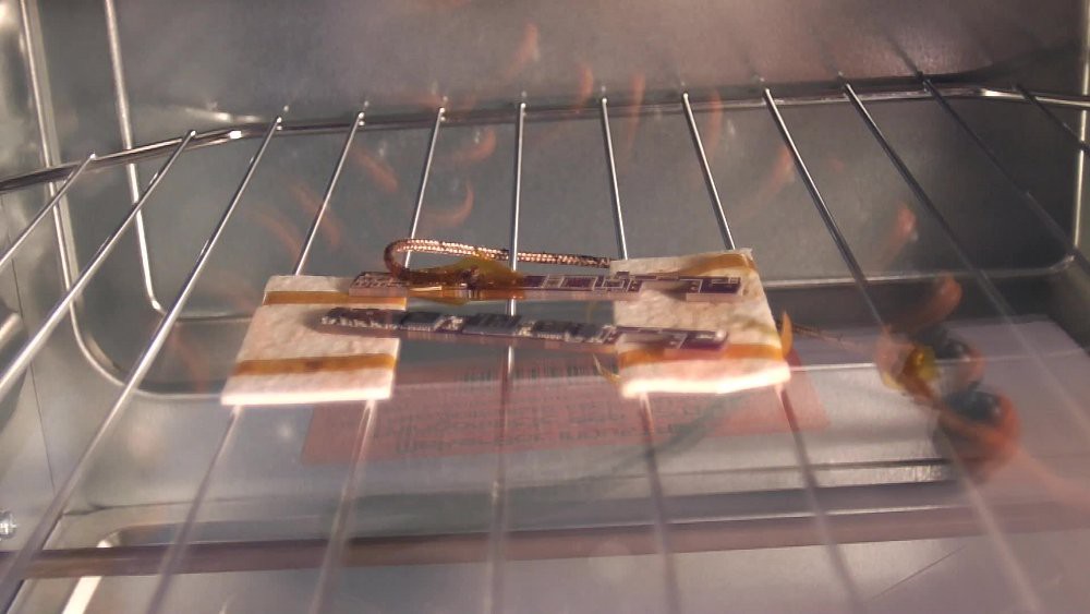
The boards were reflowed in my temperature-controlled convection toaster oven. It's not fancy: a thermocouple and on-off control of the oven are all that's needed. Ideally, the thermocouple would be attached to the board being reflowed, but trying to attach a thermocouple to a board as a dense as the NoteOn PCB would be a recipe for disaster. Instead, I taped the thermocouple to a one of the spare NoteOn PCBs and placed the actual board near it.
![]()
NoteOn Smartpen
Slim, wireless, self-contained. No special paper, no base station.