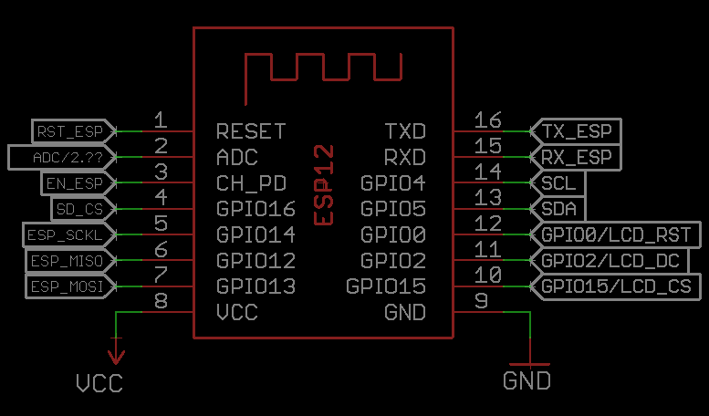
I'm currently looking into getting a sound pin and the most likely candidate right now is the LCD reset pin. Did anyone ever had any problems not using the reset pin of the Nokia LCD? What could I test to make sure it works fine? worst case scenario is turning the lameboy on and off again, I guess. I could try using RX and TX for sound, where depending on the TX state the RX would emit sound (no modem noises while uploading if done right). But if I could free the RST pin for sound, then I could use the same idea for RX and TX to transmit IR maybe. Would be cool features to have, I think.
Also to consider:
- using the D/C pin of the display for other things, maybe move to TX
- auto reset circuit for pin http://www.avrfreaks.net/sites/default/files/SSD1306_OLED_circuit.jpg
- maxim power on reset app note https://www.maximintegrated.com/en/app-notes/index.mvp/id/3227

 davedarko
Discussions
Become a Hackaday.io Member
Create an account to leave a comment. Already have an account? Log In.
https://hackaday.com/2017/10/01/trouble-flashing-your-esp8266-meet-dio-and-qio/
https://tech.scargill.net/esp8266-dio-mysteries-solved/
for reading later
Are you sure? yes | no
Switch to ESP-12F and use GPIO9 and GPIO10.
Are you sure? yes | no
Wait, that works? I thought they were unusable because they're used for communication with flash?
Are you sure? yes | no
You would have to run the SPI flash in DIO mode to get control of those pins and you would need to make sure that /HOLD (GPIO9) isn't asserted when doing SPI flash accesses, and /WP (GPIO10) isn't asserted when the flash is being written.
Are you sure? yes | no
@Sven Gregori cool, thanks for sharing that :) I currently only have tested that with a huge delay (I've placed testing the sound before initialising the display) I need to check that with a oscilloscope or digital analyzer or something - I've used the values from Radomirs link of the OLED schematics.
Are you sure? yes | no
The datasheet says:
Immediately following power-on, the contents of all internal
registers and of the RAM are undefined. A RES pulse
must be applied. Attention should be paid to the
possibility that the device may be damaged if not properly
reset.
Are you sure? yes | no
However, you might be able to do it with a simple dumb circuit.
Are you sure? yes | no
like a power on reset thing with a resistor and capacitor?
Are you sure? yes | no
Yeah, I think so. I think the popular OLED displays have a similar requirement, and the modules have that circuit on them — you could steal that.
Are you sure? yes | no
I've experimented once replacing the RST pin with an RC circuit that kept the pin low for a short time after power up, and it more or less worked.
They key is to keep the pin low long enough that the reset signal is detected, but short enough to have the LCD ready by the time your controller starts sending data to it. I didn't consider the second part at the time, so it succeeded maybe 2/3 times -- that's why the "more or less".
Are you sure? yes | no
I'm not sure GPIO0 is such a good candidate, as there is a pullup on it, and furthermore, if you have a load connected to it at boot, it might interfere with the boot process. I would put the I2C bus on GPIO0 (SCL) and GPIO2 (SDA) (additional bonus, you save two resistors, as they already have pullups), and use the GPIO4 and GPIO5 for D/C and sound (if you manage to free the RST pin). Other idea would be to use the Attiny's pin...
Are you sure? yes | no
why is the pullup not a good thing? seems like it's a good way to not have noise on the speaker? I could still invert the signal, so high means low on the speaker (?).
Are you sure? yes | no