 Doug Coffland
-
1Safety Note
Do not disassemble any part of the Dyna Myte 2400, or make any modifications to the machine unless it is turned off and unplugged from the AC source.
-
2Remove the old touch panel
The touch panel was already removed on this unit. If yours is still there remove the panel and the mounting bar from the machine. Then, cut the multi-conductor cable that goes from the touch panel to the driver board, and remove it. Save the grommet as this perforation will be used for power wiring.
-
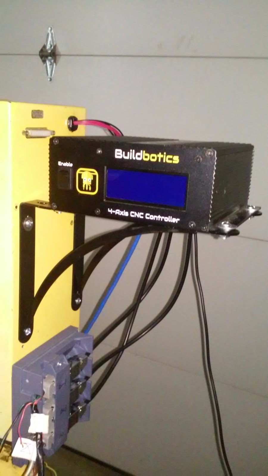
3Mount the Buildbotics CNC Controller to the side of the existing control cabinet.
Attach the controller to the side of the original control enclosure using two 9"x6.5" right angle shelf brackets from the local hardware store.
You'll need to drill some holes in the side of the existing control enclosure. Then attach the brackets to the side of the enclosure and attach the Buildbotics controller to the bracket with appropriate nuts and bolts.
-
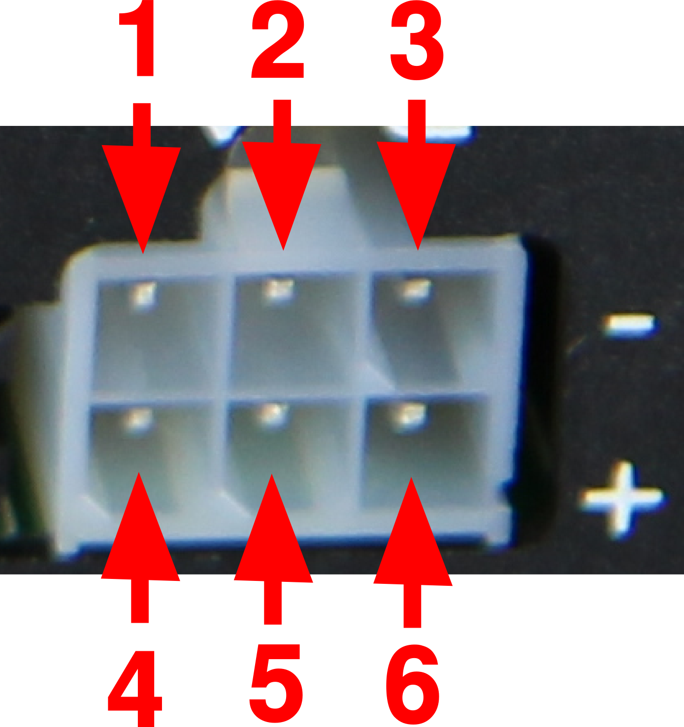
4Connect the power wiring from the existing power supply to the Buildbotics Controller
Power is supplied to the Buildbotics Controller through the 6-pin molex connector on the back. When connecting to this connector, be sure to connect ground to pins to the top row (pins 1, 2, and 3) and the working motor voltage to the bottom row (pins 4, 5, and 6). The working voltage can be anywhere between 12 and 36 Volts DC. The Buildbotics CNC Controller has reverse battery protection, so getting this backwards probably won't hurt it, but then hooking up power backwards is never a good idea. Also, connecting power and ground to pins 1, 2, and 3 or pins 4, 5, and 6 simultaneously will provide a short circuit with unpredictably bad results.
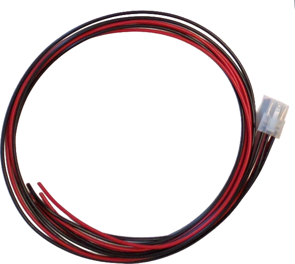
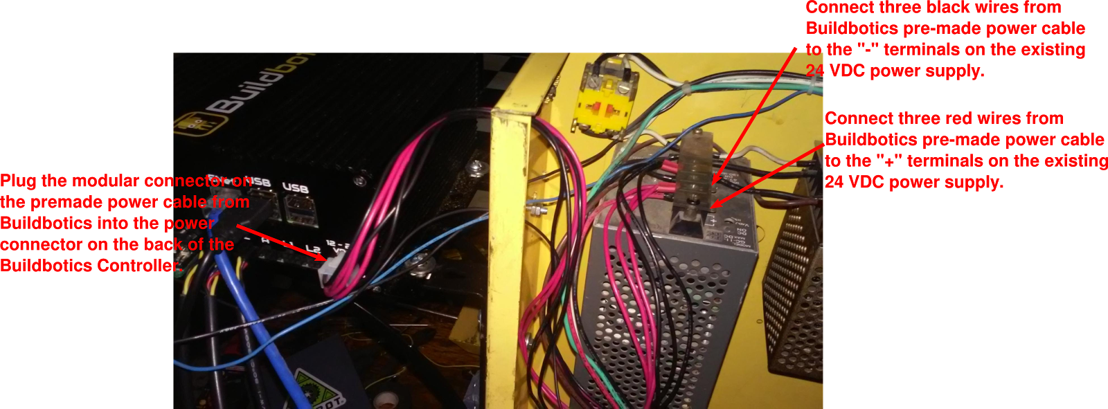
The existing DC power supply is rated at 24VDC at 4.5Amps and is acceptable for this application. Connect power using the following procedure:
- Plug the pre-made power cable into the back of the Buildbotics Controller.
- Feed all six conductors through the hole left from the touch panel display multi-conductor cable. Re-use the grommet from that cable to protect the new power wiring.
- Connect the three red wires on the pre-made power cable to the “+” terminals on the existing power supply.
- Connect the three black wires to the “-” terminals on the existing power supply.
-
5Connect the motor wires
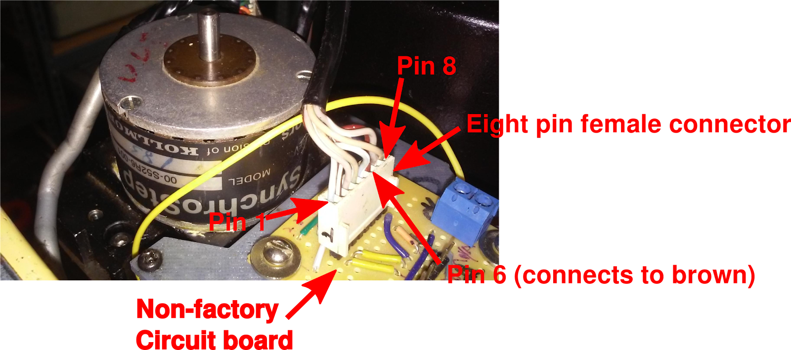
The motors on all three axes are SynchroStep Model 00-S52R6-00 8-wire stepper motors. The goal is to wire them as bipolar and parallel.
Eight wires emanate from the motor and are presented on an 8-pin, female connector. Unfortunately, the wire colors had faded out on this machine and the only color that was identifiable was brown, which is pin 6. This allowed determining the rest of the pin numbers based on the table below.
Stepper Wire Color Designation Pin # Blue A 1 Brown/White A'- 2 Grey B 3 Green/White B'- 4 Brown/White A- 5 Brown A' 6 Grey/White B- 7 Green B' 8 It has also been reported that the color coding may not be the same from one machine to the next. If there is doubt about the color coding, use an ohmmeter to measure continuity through the coils. For instance, pins 1 and 5 make up coil A and should appear shorted to each other and open with any other pins.
The picture shows a yellow circuit board. This was installed by the owner, and your machine is not likely to have this. The owner used this board to interface to the existing harness that routes inside the machine and then terminated those cables on DB9 connectors in a box on the side of the control cabinet.
The following pictures shows the motor connectors on the Buildbotics Controller and the pre-made cables available from Buildbotics.
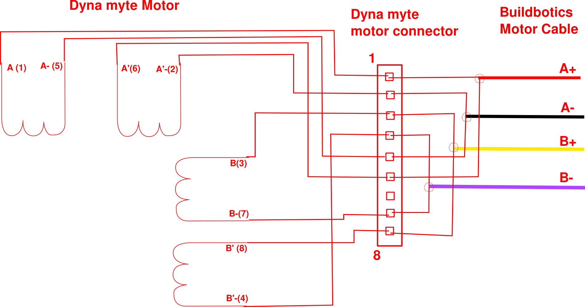
Plugging a Buildbotics pre-made cable into a motor jack on the back of the Buildbotics Controller presents the motor driver wiring as shown in the following table:
Coil lead Cable wire color A+ Red A- Black B+ Yellow B- Purple A stated above, bipolar and parallel connections are desired. The following wiring diagram shows the connections that must be made for bipolar and parallel.
![]()
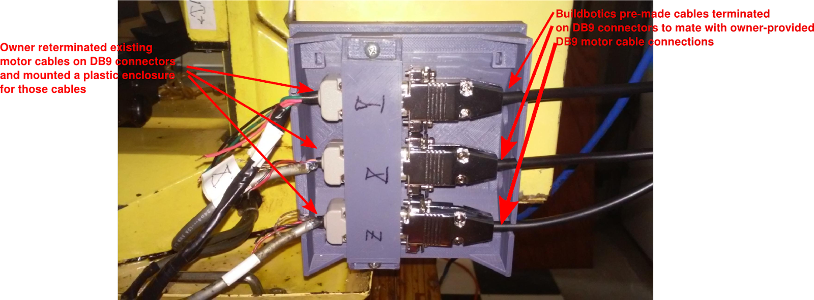
It is recommended that the existing motor cabling be re-used. This prevents either having the cables exposed outside the machine or disassembling the machine in order to run the cables internally. For this build, the Buildbotics pre-made cables were terminated in DB9 connectors which mated with the owner-installed DB 9 connectors.
-
6Connect the spindle wiring
The Buildbotics Controller has the ability to turn the spindle on and off by issuing M3 and M5 G-code commands respectively.
Safety Note - The Spindle ultimately gets turned on using an active low output from the Buildbotics controller. This active low is not asserted until the controller has booted. As such, the spindle will come on for several seconds during the system boot process. To avoid any injury that could be caused by the spindle unexpectedly coming on, it is recommended to always keep the On/Off switch on the side of the spindle housing in the off position when not cutting. Only turn that switch on when you are ready to start cutting, when people are clear from the machine, and when no foreign objects are near the spindle.
The spindle wiring connects to three pins on the DB25 connector on the back of the Buildbotics Controller. A DB25 breakout board is required. Furthermore, since the DB25 connector on the Buildbotics Controller is male, the breakout board must be female. The following image shows the pin-out on a DB25 breakout board.
Use the following procedure to connect spindle on/off control from the Buildbotics Controller to the Dyna Myte 2400:
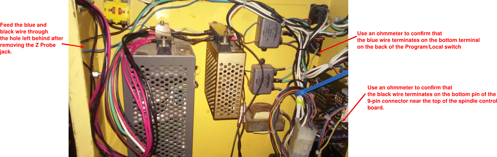
- Find the three pin connector that was previously connected to the motor driver board. That specific connector of interest has two wires connected to it. They are black and blue wires. Cut the connector off of these wires (leaving the wires as long as possible) and strip wires back about ¼”. Verify that you have the right wires by using an ohmmeter to confirm that the blue wire connects to the bottom terminal on the back of Local/Program switch and that the black wire terminates on the bottom pin of the 9-position connector at the top of the spindle control board.
- Connect a ground wire (preferably black) to the “-” connector on the 24 VDC power supply.
- Remove the Z-Probe cable and jack from the control cabinet and feed the ground wire, the black wire, and the blue wire through the hole left behind from the Z-Probe jack. Use a grommet to protect the wires.
- Connect the ground wire to a Gnd (Pin 18) on the DB25 breakout board.
- Connect the blue wire from the back of the Program/Local switch to a 3.3V terminal (Pin 20) on the DB25 breakout board.
- Connect the black wire coming from the spindle control board to the Spin Enable terminal (Pin 15) on the DB25 breakout board.
- Attach the DB25 breakout board to the back of the Buildbotics Controller.
Note - you may have to remove the black and blue wires from the wiring harnesses to allow them to be long enough to reach the DB25 breakout board when it is attached to the back of the Buildbotics Controller.
-
7Connect the limit switches
The Dyna is equipped with three limit switches; one on each axis. These limit switches are used for homing the machine.
This picture shows the z-axis limit switch. When the two parts of the limit switch come together, the z-axis is at its highest position and the circuit is closed. The X and Y axes limit switches close when the axes are in their minimum position. These closures signal the controller when limits are reached by connecting the active low input limit switch inputs to ground. The limit switches on all three axes work the same.
In order to connect the limit switches to the Buildbotics controller, you must connect all three ground wires to a ground pin (pin 25) on the DB25 breakout board. Then connect the other side of the limit switch to the appropriate limit switch input on the DB25 connector as follows:
- XMIN Limit switch - pin 4
- YMIN Limit switch - pin 5
- ZMAX Limit switch - pin 10
Note that the original wiring has these wires in the same sheath with the motor wiring and you may be able to split them out from the cable sheath and hook them up. Unfortunately, the wiring on this machine was in pretty bad shape resulting in false closures due to noise. I fixed this problem by running wires serving the X and Y axes limit switch inputs outside of the machine from the limit switches to the motor housing and then back to the terminal box and up to the DB25 connector. These connections were neatly run outside the machine.
-
8Z Probe wiring
Many machines benefit by having a Z-Probe for setting the cutting height of the Z axis. The Dyna has an excellent feature that allows easily adjusting the height of the cutting bit simply by releasing the lock on a "quill" and moving the height to the exact desired level. As a result, no Z-Probe is needed.
If you want to use a Z-Probe, connect a touch plate or probe to the probe input (pin 22) on the DB25 connector.
-
9E Stop Wiring
The Dyna comes with an E Stop switch that is connected in line with the input AC. As a result, no additional E Stop switch was necessary for this retrofit.
If you want to connect another E-Stop switch, simply connect the E Stop switch to ground (pin 25) and Estop (pin 23) on the DB25 breakout board.
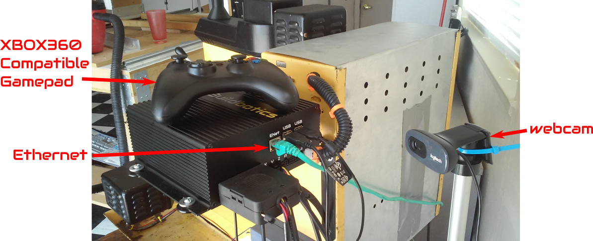
Connect local network, game pad, and webcam
Connect to the local Ethernet by plugging the network cable into the RJ-45 jack on the back of the Builldbotics Controller. Connect the XBOX360 compatible game pad and a Raspberry PI compatible webcam (if desired) to any of the USB ports on the back of the Buildbotics controller.
Configuration Preparation
Power must be applied to the Buildbotics controller and the controller must be attached to a local Ethernet subnet for configuration. Since the Buildbotics controller is powered from the 24 VDC power supply inside the Dyna Myte 2400, the 2400 must be plugged into 120 VAC power and the red power switch on the 2400 must be switched on. After plugging in the 2400 and turning it on, verify that the spindle Off/On switch is off and switch the Enable switch on the Buildbotics controller up to allow the system to boot. Once booted, the LCD panel will display the work “Ready” in the upper left corner (among other things).
When the Buildbotics controller is “Ready” it can be accessed and configured as described in the Buildbotics Controller Manual.
Connect to the Buildbotics Controller
Open up a web browser on any computer that is connected to the same local network as the Buildbotics controller and enter "bbctrl.local" in the address line. A page similar to this will open.
-
10Connect local network, game pad, and web cam
Connect to the local Ethernet by plugging the network cable into the RJ-45 jack on the back of the Builldbotics Controller. Connect the XBOX360 compatible game pad and a Raspberry PI compatible webcam (if desired) to any of the USB ports on the back of the Buildbotics controller.
CNC retrofit with a Buildbotics CNC Controller
This project demonstrates retrofitting an old CNC Mill with an ultra-modern, Open-Source CNC Controller


Discussions
Become a Hackaday.io Member
Create an account to leave a comment. Already have an account? Log In.