 Saimon
-
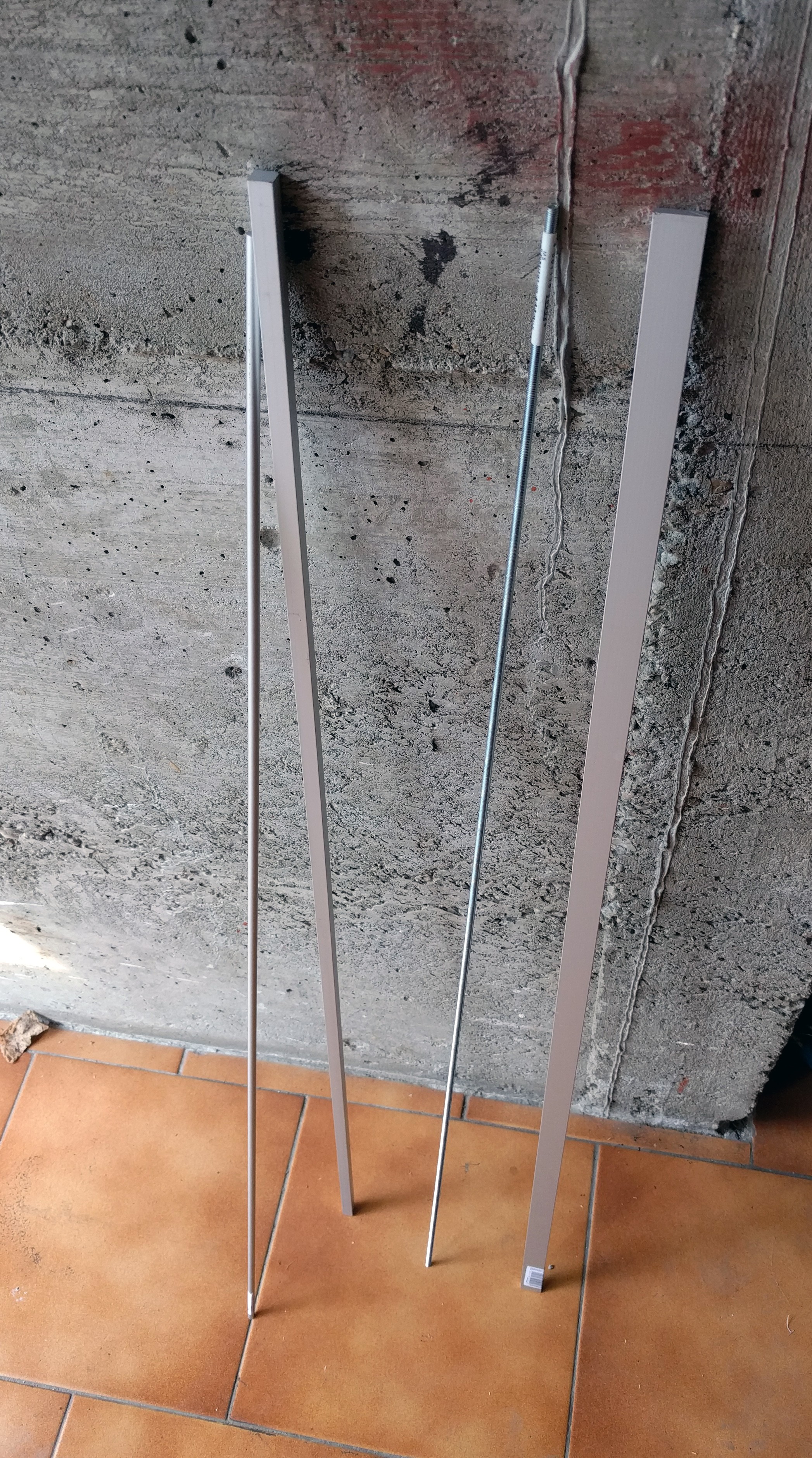
1Material
The materials to make this PCB holder are aluminum, except for the threaded bar that is in iron. I used 3 types of rods:
![]()
- Round with a diameter of 6 mm
- Squared 10 x 10 mm
- Rectangular 20 x 5 mm, that are used for the jaws
Plus the threaded bar with a diameter of 5 mm.
-
2Cutting the rods
From the rods, i have cut several pieces:
- From the squared rod, 4 pieces that are 8 cm long
- From the rectangular, 2 pieces that are 10 cm long
- From the round, 2 pieces 22 cm long
- From the threaded bar, one piece 24 cm long
-
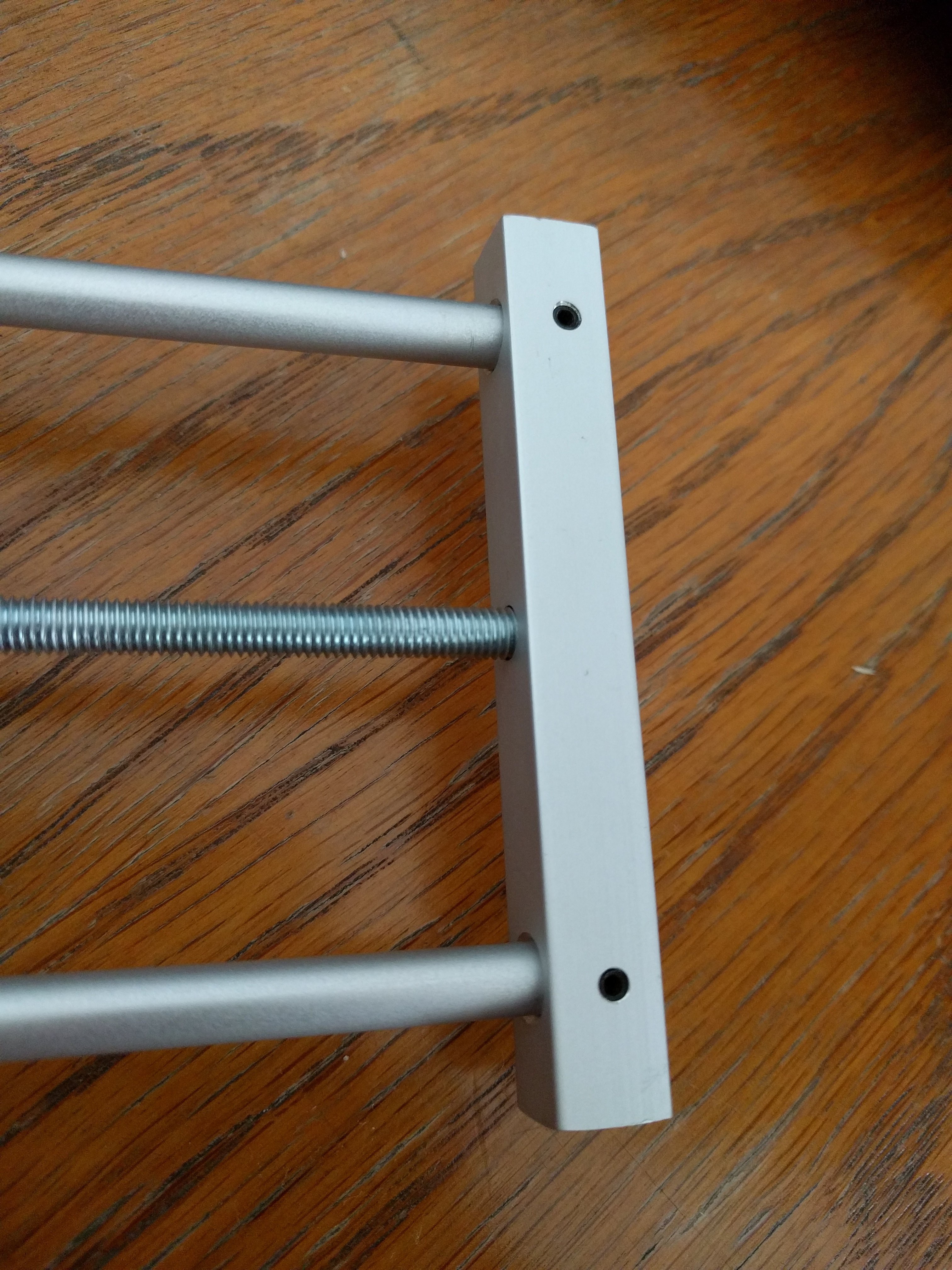
3Drill the pieces
With the drill press, i made several holes:

There are 2 holes of 6 mm made at the two edges, for the tow squared rod that have to be fixed at the round rods. There is also one hole of 5 mm in the center for the threaded for one is a blind hole.
For the other tow squared rod, that have to slide, i made 2 holes of 6.5 mm at the edges, and one rod have the 5 mm hole in the center, while the other have the thread hole in center for the threaded bar.
I made also the same holes on the jaws and the slots to hold PCB with a V shape rasp. The jaws are connected with 2 screws of 3 mm.
The round rod are fixed to the square rod with a small grain
![]()
-
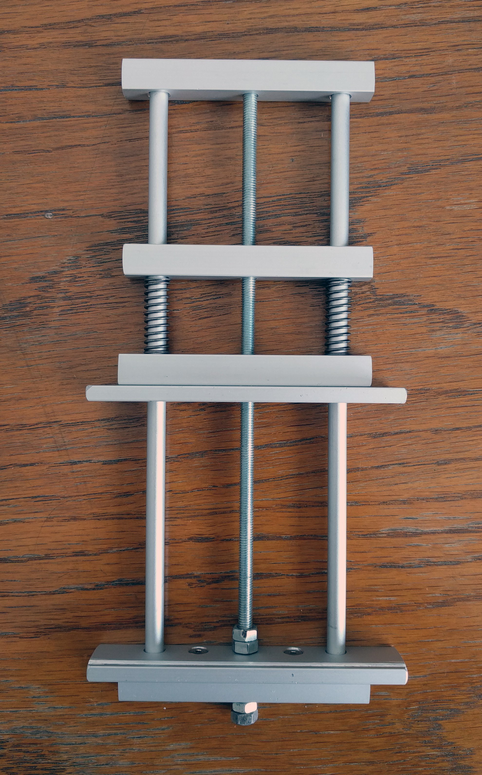
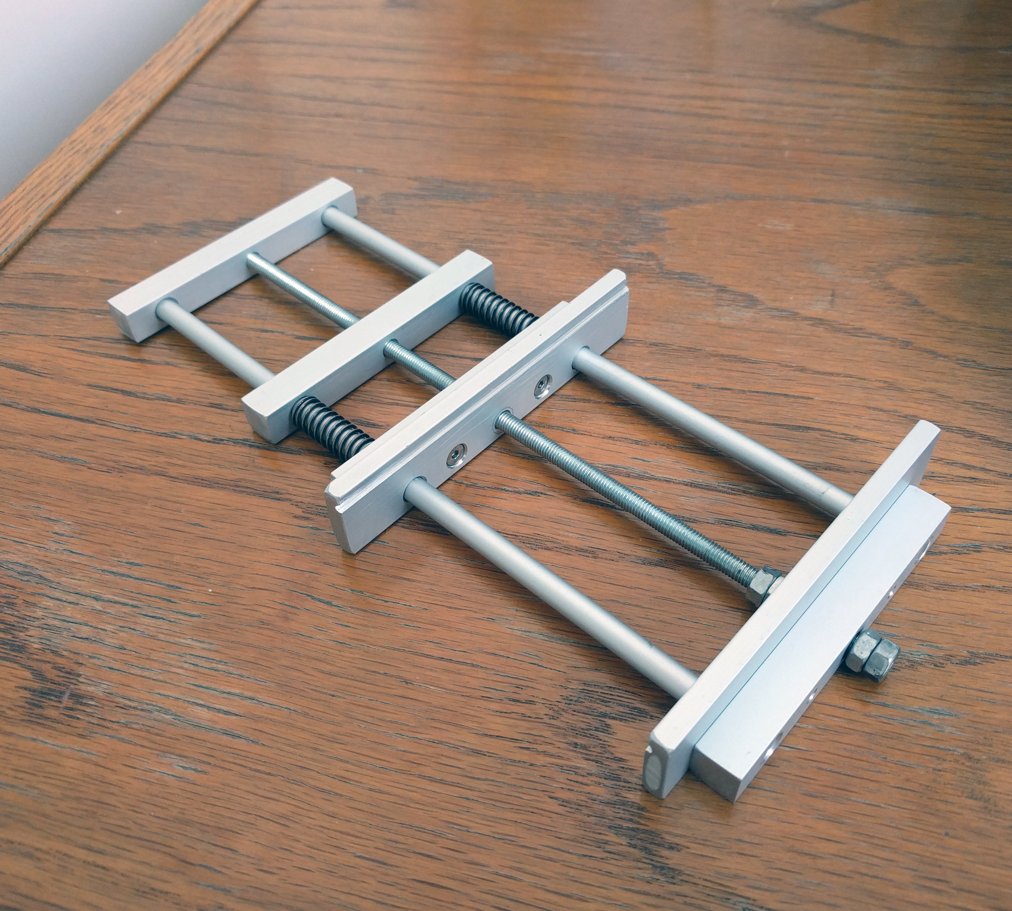
4Assembly
At the end, all the pieces are assembled.
![]()
![]()

Discussions
Become a Hackaday.io Member
Create an account to leave a comment. Already have an account? Log In.