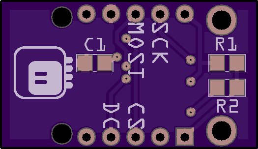
After a hint from @limor about a reset pin and some experimenting, I decided to re-do this PCB, this time properly, following all the rules.

So the reset pin is now tied to the board's reset. That frees up one digital pin, which I can now use for chip select, instead of having it pulled down permanently. Because the Trinket M0 doesn't have a pull-up resistor on its reset pin, I had to add one.
The second resistor is for the LED back-light, so you can pick the right one for the brightness you desire.
Finally, I added a filter capacitor to the display's power, for good measure.
I also fixed the mounting holes and added a logo. The logo is up-side-down in relation to the text on the board, but I only noticed it now and who looks at those things anyways.
 deʃhipu
Discussions
Become a Hackaday.io Member
Create an account to leave a comment. Already have an account? Log In.
hmmm.... https://hackaday.io/project/11551-hackadaybashorg/log/66247-oshpark-driven-development
Are you sure? yes | no
Guilty as charged.
Are you sure? yes | no