Close
0%
0%

HaptiVision

A haptic vest for orientation for the blind

Similar projects worth following
Haptic feedback systems for helping blind people to orient themselves exist and are researched for a while. The combination of a depth camera and vibration motor arrays e.g. done by Sean Benson (https://hackaday.com/2014/09/21/thp-semifinalist-a-haptic-vest-with-48-vibration-motors/) seems to be promising to help blind people to get a feeling of their surrounding. In 2015 one of our students, David Anton Sanchez, built a similar system (http://hci.rwth-aachen.de/openvnavi), with 16*8 motors. In the Personal Photonics project, sponsored by the german federal ministry of education and science we are now on the way to make this vest rebuildable as easy as possible for everyone as open-source project

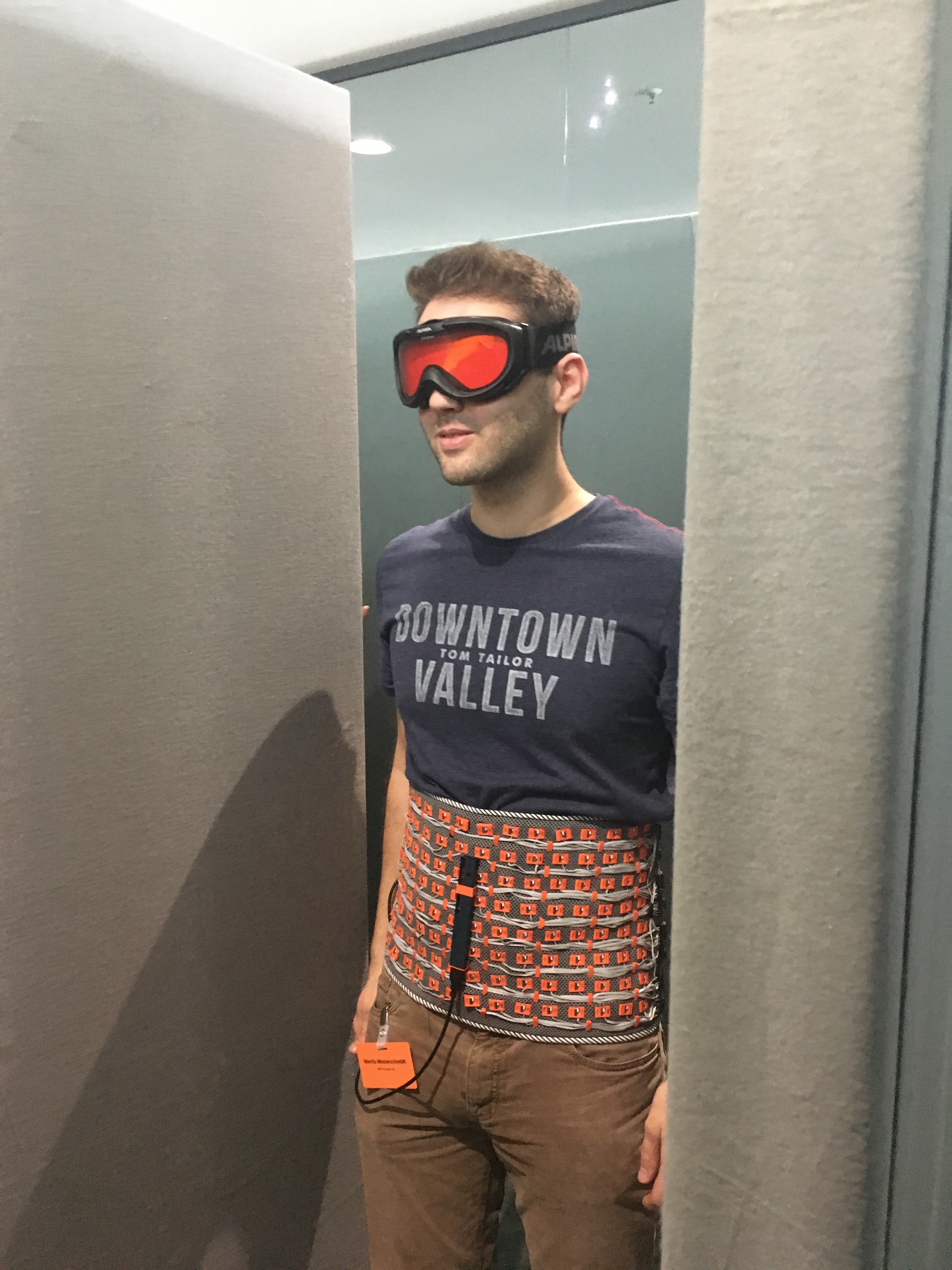
The main concept is the same as in David Benchoffs and David Sanchez vest: Using an array of vibration motors controlled by an image from a depth camera - so each vibration motor acts as an image pixal and vibrates stronger the nearer an object is at this pixel position, helping the visual impaired to get a feeling of their surroundings and know where to go and where not.

Since the vibration motors can be worn under the clothing, the system is (normally) invisible besides the sensor system, and uses with the abdomen an otherwise unused sensor channel, not disturbing other already used for visual sensory substitution.

Instead of the Kinect or the smaller Asus XTion we used a Intel Realsense camera, mainly because the camera is still a bit smaller. This sensor system is now the part which still needs rework because of the inherent problems of the infrared based camera: Sensor angle, problems with sunlight, and the non-detection of glass.

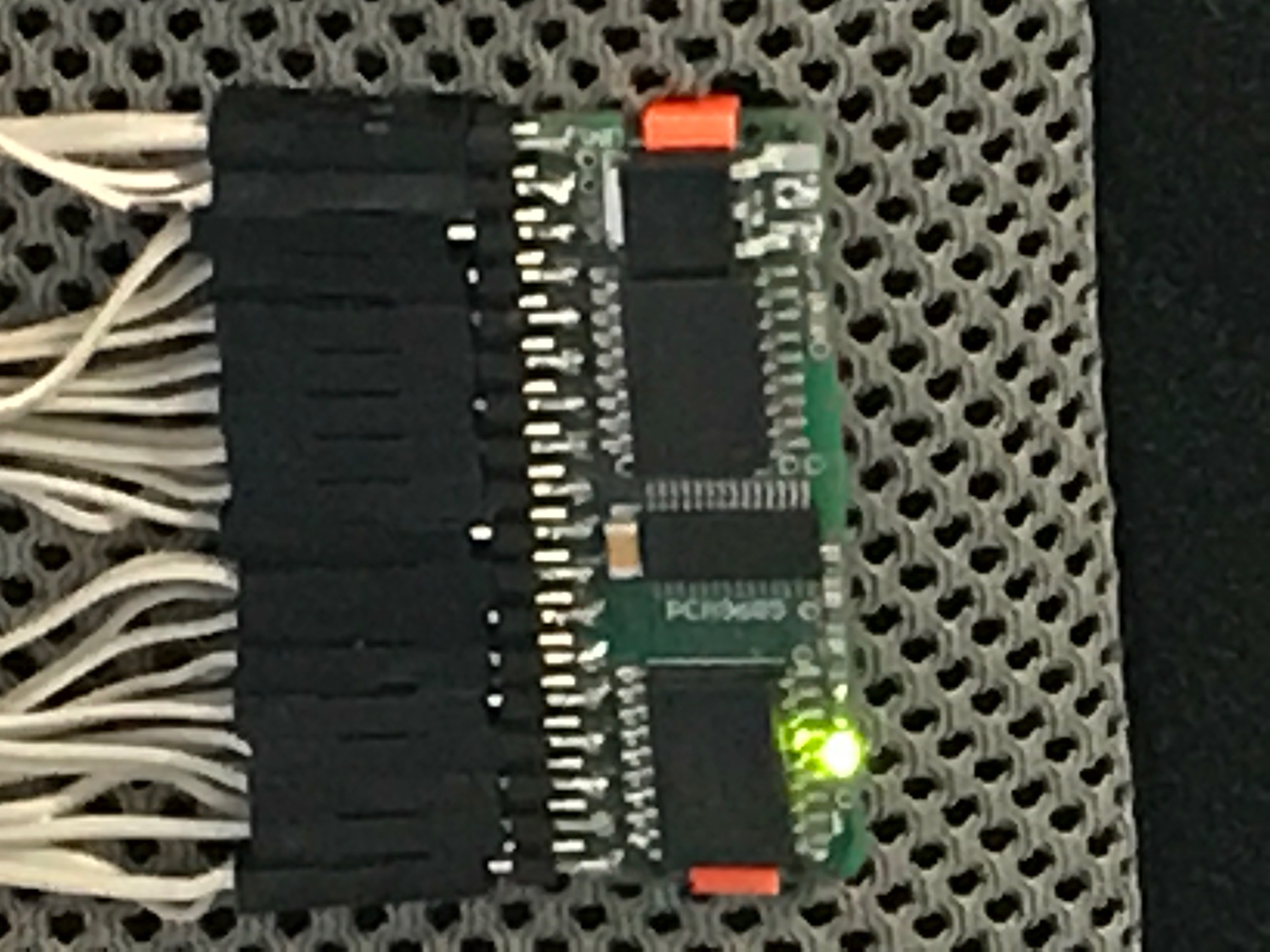
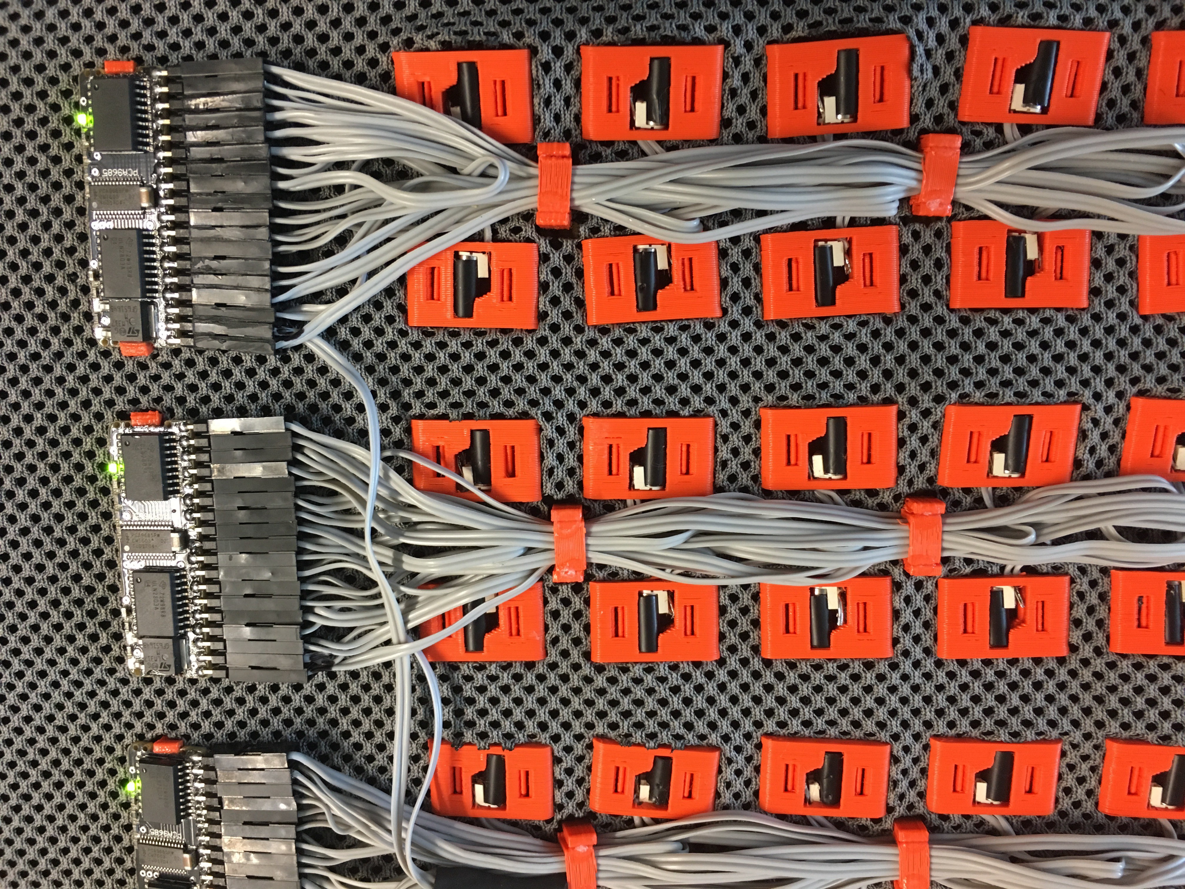
An Up board was used instead of the Pi for camera processing, just because it was the system recommended for the Realssense camera (intel robotics kit). Data is then send by I2C to eight custom-made PWM expander boards (based on the Adafruit Servo expander boards), but including both a PCA9685 and the necessary driver for the motors. Each board further includes a voltage regulator, allowing the system to be fed by a normal 5V power bank.

For easier rebuild, all encapsulations are made by a standard FDM 3D printer, and wiring with normal flat wire and crimp contacts / pin header on the driver board (could be also replaced by just soldering).

Motors (and driver boards as well as cable routing) are held in place with the 3D printed clip form in corresponding holes in the textile for a clean setup.

Since weight is evenly distributed the only heavy component remains the power bank, and instead of a belt system we used allow multiple persons to test the system on faires with quick changes, one could normaly just use a tight textile, make the holes into and mount the electronic.
  • Customizable motorcasing

    Rene Niewianda09/05/2017 at 15:40 0 comments

    In order to use different sizes of rumble motors a new casing type was added. This one is now fully customizeable, it fits almost for every motor. Other customizeable parameters beside the dimensions of the motors are for example the depth of the walls or an offset so thicker fabtic can be used. All options that can be changed are commented in the scad-file, in order to explain what they will change.

    The scad-file also contains a test-method to check if everthing was scaled correctly, because in the case that the motor ist very large the clippers might be to thin to keep it in place.

  • Bee swarms and power consumption

    JanThar09/03/2017 at 20:38 0 comments

    One importand part to consider is that vibration motors make noise, something which isn't intended and should be reduced as far as possible. it will otherwise undermine the invisible tool effect of the vest, might cause confusion on nearby people and will disturb the audio channel of the wearer, who might want to use it also for orientation (bat echolot). With the first version, we had a big issue with sound, we even made a sign on one exhibition with a warnign "bees inside", since whenever sombody passes the vest on short distance, most of the motors went on full power and gave a corresponding sound.

    With the next version we had less coupling effects between the motors, and for using a normal power pack with limited current instead of a racing battery pack we also had to reduce power consumption. Therefore we decided to drive  - apart from the normal PWM driving of each motor - only few motors at the same time on each driver circuit, drastically reducing both power consumption and noise.

    At the moment each half of the vest (64 vibration motors and their driver circuits) is powered with  one 1A USB port of the power pack, Realsense and Up-board on another 2.4 A port - with a 18200 mAh power bank we could run the system for almost 8h on exhibitions, with  a neglectable noise level.

  • Curse of the depth camera

    JanThar09/03/2017 at 20:23 0 comments

    The whole systems works well on exhibitions: High tables and standing persons result that the camera opening angle is not as bad as in real life. Our basic example for a real life problem with this angle is always something in head area: with the belly-mounted camera the system will warn you if it is far away that you will have to duck through vibrations in the upper part of the motor array, but when the object is directly in front of the person the camera will look below it and won't warn the wearer anymore. An more obvious problem is glass: While the user trust the system quite fast good enough to walk around with closed eyes, at some point dependent on the location they where straigth moving into glass fronts or mirrors, if we wouldn't stop them. Another problem not shown on exhibitions is that the infrared based camera system won't work in sunlight, reducing the usability drastic.

    Our intended solution is in the next step adding additional ultrasonic and lidar system for the near range, if we can build a system with fast enough response time on ultrasonic basis as a sort of rough 3D scanner, we might try to replace the camera system as most expensive part of the system complete, or at least reduce it to an optional add on.

  • Motor driver evolution

    JanThar09/03/2017 at 20:08 0 comments

    Goal was a small driver board which only need power supply and I2C and then drives 16 motors at once. In several iterations we found out that the best way was to have all I/O pins on one side, both for size and later wiring. Furthermore, having two pins (one on each side of the board) drastically reduces complexity of wiring and faults compared to the first intended common ground wire, where all motors share one wire.

    A variable voltage converter can supply the board with the 3.3V necessary for the here used vibration motors, and can be supplied e.g. a normal 5V power bank. Since the regulator is directly on board of the driver board, the system is scalable to even bigger (or smaller) vibration motor arrays. Board layout and 3D-design files can be found here.

  • Vibration motor choice

    JanThar09/03/2017 at 19:54 0 comments

    For a first iteration of the vest (or now belt) we found some nice encapsulated vibration motors - but they are no longer available. Pancake motors, which we wanted to use first, where not that reliable on the long run, and hard to solder. Our vibration motor of choise is now a standard, as small as possible vibration motor with external excenter (because they are easy to get :). To prevent the excenter to stuck in the pla of the housing, we make our own small encapsulation with a piece drinking straw (the excenter should be therefore have a smaller diameter as the motor housing, which should be a little bit smaller than the (5mm) straw diameter). The second importand choise are the electrical connectors of the motor: Wires are annoying, because they have to insulated. We chose instead motors with a spring connector at the end, which allows reliable soldering (with just small pads on the motor it might be prone to breaking) and will be encapsulated within the housing, preventing the need of additional isolation.

View all 5 project logs

Enjoy this project?

Share

Discussions

JanThar wrote 09/12/2017 at 00:53 point

Correct and corrected - and that was embarassing because i got your name right beforehand, e.g. citing you in the text in the upcoming ISWC2107 design exhibition (http://iswc.net/iswc17/program/designexhibition.html), only excuse might be it was a last minute write down. Sorry for that. We are aware that the resultion is a bit to good -  on one hand we argue with fault tolerance if some motors break down, more importand we want to test the belly threshold on the long run (to test if we can get something like learning effects to distinguish a slightly better resolution). But most importand thing to now is improving the sensor system.

  Are you sure? yes | no

Sean Benson wrote 09/11/2017 at 22:13 point

JanThar,

I am glad that you are making a new version of my project!!! Although in the second sentence of your description you misreferenced the maker of the Vest! "The combination of a depth camera and vibration motor arrays e.g. done by Brian Benchhoff (https://hackaday.com/2014/09/21/thp-semifinalist-a-haptic-vest-with-48-vibration-motors/) "

I, Sean Benson, made this project, "3D Haptic Vest for Visually Impaired and Gamers".  I understand the confusion because Brian Benchhoff made an article of my project for the Hackaday blog. Please update your description to the correct reference, "Sean Benson." 

Keep up the great work!!! I want as many visually impaired people as possible to get their hands on this. It is just that I have WAY more important projects to work on for the benefit of humanity.

P.S. Your motors look like they are too close. The two point discrimination threshold for the skin on the torso is about 2".

Thanks, 

Sean Benson

  Are you sure? yes | no

Similar Projects

Does this project spark your interest?

Become a member to follow this project and never miss any updates