visualkev
-
Field tested, crowd approved
07/03/2018 at 16:32 • 0 commentsSince my last log, the sequencer has been used for New Year's 2018 and Independence day 2018 festivities. It worked as planned and everyone enjoyed the shows. My friend who i created it for is also quite pleased with it and now he enjoys designing his pyrotechnic displays.
A possible future version that has been discussed is the ability to coordinate the display with a music track. I've also been pondering control from a PC/tablet/smart phone.
![]()
Setup for New years 2018 -
Chasis aquired! Layout begins.
10/21/2017 at 17:27 • 0 comments![]()
I found a used rack mount drawer assembly, 3U. Its plenty big, it's metal for durability and the electronics are completely enclosed when the drawer is closed. All the components in the box will be mounted to the piece of medium density fiberboard, MDF, in the bottom of the box. I'm still deciding on final positions of everything before i cut out slots for the igniter leads to exit the enclosure.
-
Integration testing going very well
10/08/2017 at 22:28 • 0 comments![]()
The board is fully populated and testing with half the relay boards is 100% perfect - A pleasant surprise. I've build the 5V regulator circuit board, thats the proto board pictured center frame, cleaned up the wiring from the remote board, its the board in the left of the image with the yellow tape. The arduino programmed without issue through its programming pin header.
The next steps:
- Finish testing with all relay boards
- Plan the chassis
- Make electric matches
-
PCB's Have Arrived!
10/06/2017 at 04:16 • 0 comments![]()
PCB's have arrived and I've got it mostly stuffed. The 28 pin socket is on order. I hope to have it by the weekend. Then i can fire it up and see if smoke comes out...or does nothing at all. -
Breadboard the arduino circuit
09/25/2017 at 03:06 • 0 comments![]()
Today I've breadboarded the arduino circuit and power supply. I was able to successfully send and run the blink sketch. Yes I got the process backwards; I've breadboarded after laying out and ordering the PCB, but the circuit looked simple enough that I felt lucky enough to go for it. My PCB goes to fab tomorrow and I can't wait to get it on my bench, test it out and see how close I got it to functional.
-
Control board plan B
09/20/2017 at 05:07 • 0 comments![]()
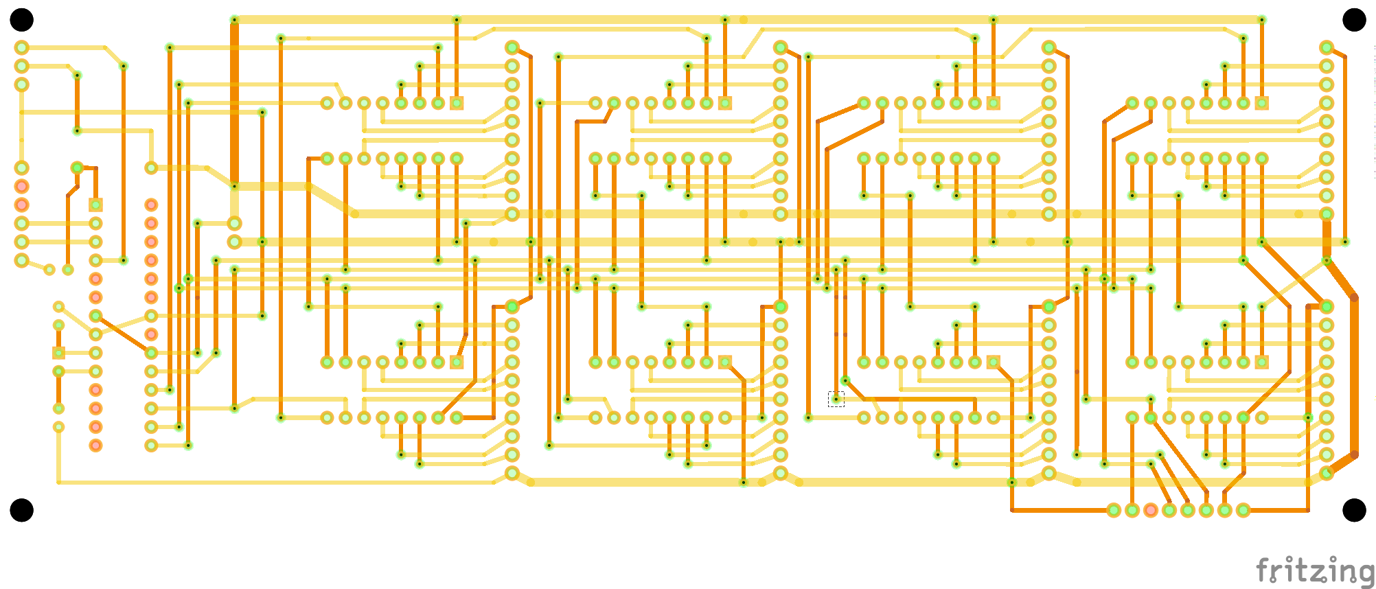
I tried hand wiring the control circuit on a proto pcb. It was tedious and didn't look very good. I gave up on that and drew it up in Fritzing and ordered a set of 3 from Osh Park.
![]()
Hopefully the boards are not too messed up. We shall see.
-
Control circuit block diagram snippet
09/17/2017 at 20:02 • 0 comments![]()
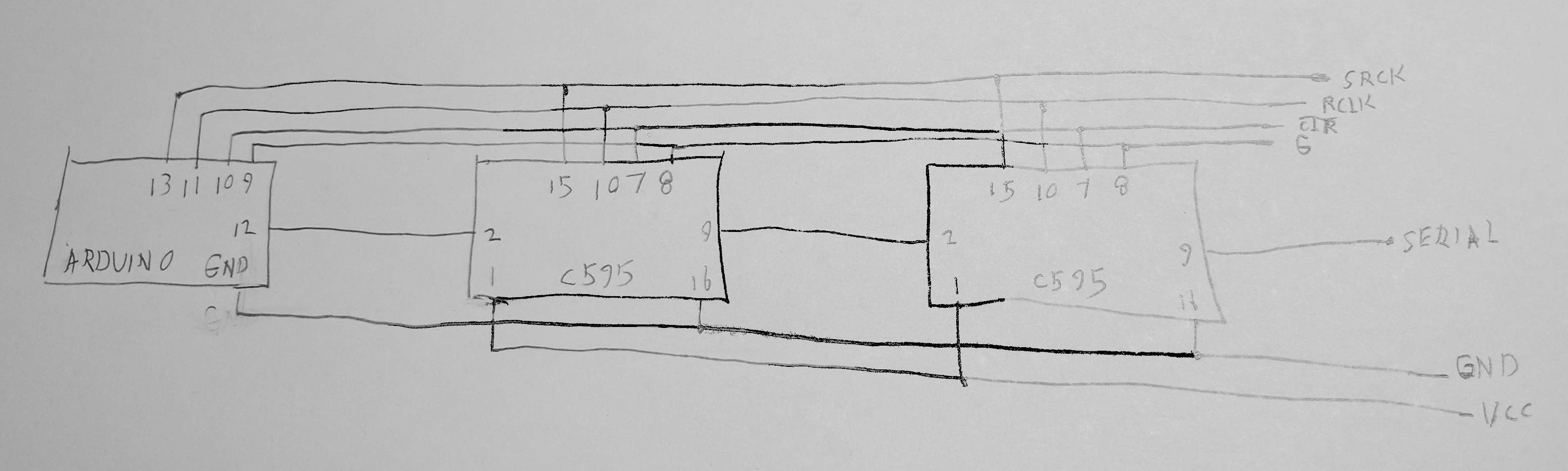
This is a quick block diagram of the control circuit.
-
Driver board update
09/15/2017 at 03:31 • 0 comments![]()
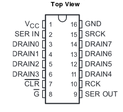
This is the pinout for the Texas Instruments TPIC6C595. It can actually drive small inductive loads such as my 5v relays, but since i found the premade relay boards, they will only be driving an opto-isolator. I still have not decided on the design for the circuit layout for these driver boards. The red proto boards may not have enough pins for everything. I want the driver boards to be stackable, so must ponder it further.
-
Relay board mods complete
09/11/2017 at 05:24 • 0 comments![]()
I've finished the modifications to all eight relay boards finally, namely jumpering all the relay poles together and changing the 10 pin header from straight to right angle. I think the next step will be to build a control board, test it and repeat for a total of four. The control board holds 2 shift registers and a pin header for each which will connect to its relay board.
In the midst of thinking through the above, I am also pondering the chassis layout. Maybe a plywood base and an aluminum cover with access doors to the relay terminals - design pics coming at some point.
Pyrotechnics sequencer with wireless trigger
This device will light fireworks in sequence with a wireless remote. Version one will have 64 positions