 jason.gullickson
-
Come Play Between the Lakes
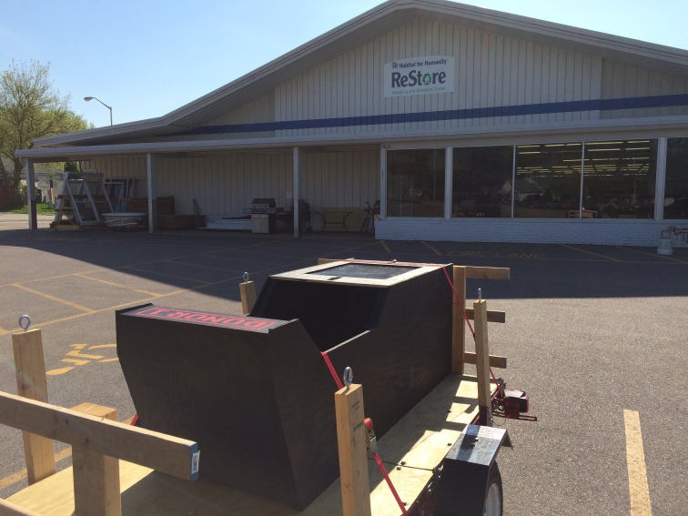
05/18/2018 at 17:33 • 0 commentsGoodbye ReStore,
![2018-05-16 16.54.01]()
This week, DONOR-1’s stay at the Beaver Dam Habitat for Humanity ReStore came to a close. We are very thankful of the ReStore for hosting DONOR-1 through the winter months, but now that the snow has finally melted it’s time for a new adventure.
Hello Madison!
We’ve heard from a lot of people who want to check-out DONOR-1 but didn’t find themselves near any the places who have hosted us so far. I’m very happy to announce that Horizon Coworking has offered to host DONOR-1 in downtown Madison, Wisconsin!
![2018-05-16 18.45.17]()
Conveniently located right on the capital square, Horizon is accessible by foot, bike, bus and car and should make it easier for more people to get a chance to play and support some local organizations.
Speaking of which, DONOR-1 will be raising funds for a number of Madison organizations during its time at Horizon, beginning with Domestic Abuse Intervention Services (DAiS).
In addition to being a great place for DONOR-1 to live for awhile, we’re noodling on new ways to collaborate with the folks at Horizon to explore new ideas we have for this machine as well as how we can find more ways to use technology to support work for social good.
Horizon Coworking is located at 7 N Pinckney Street, Suite 300, Madison, WI. Take the front stairway (or central elevator) to the third floor and follow the hall toward the back of the building (or turn left when you exit the elevator). You’ll find DONOR-1 among the tables and couches lovingly referred to as the “Nerd Deck”. Be sure to bring some quarters (50 cents per game)!
Hope to see your initials on the scoreboard!
-
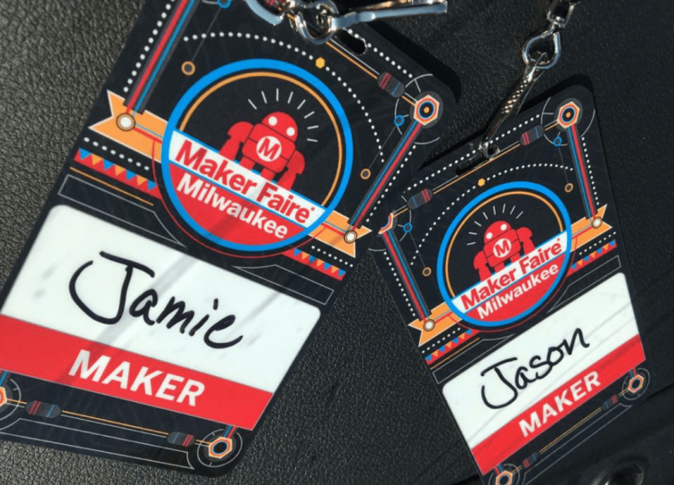
DONOR-1 goes to Makerfaire!
10/06/2017 at 14:17 • 0 commentsA couple weeks ago DONOR-1 took a roadtrip to Milwaukee Makerfaire!
![img_6320-e1507298900939.png]()
The excitement began with a very nice write-up of the project (as well as some other things we’ve worked on) in a Maker Spotlight post on the Make Magazine blog.
Friday night before the faire we headed to The Idea Studio to pick-up the machine. The Idea Studio was a great place to host DONOR-1 and the crew there was sad to see it go.
![IMG_1525]()
After figuring out how to fit three people, the control panel, a dolly and assorted other bits into our little Jeep, we strapped DONOR-1 to the trailer and headed home.
Saturday morning we hit the road early to make it to the fairgrounds before 8:00AM. This was my first experience driving around Milwaukee with a trailer and it wasn’t as bad as I expected. That said we still managed to get a little lost (Milwaukee likes to move their roads around) so we were a little bit late to the faire.
![IMG_1529]()
DONOR-1 was a stand-alone exhibit which means we got a chance to check-out the rest of the faire this year. That being the case we didn’t get to meet everyone who checked it out, but we grabbed a few snapshots and received some photos from friends who played it after the faire.


Sunday afternoon I headed back to the faire to pick-up DONOR-1 and was pleased to see it was not only operational, but there was even a line of people waiting to play! I waited about 45 minutes for a break in traffic to shut it down, but eventually I just had to get in line and wait my turn to switch it off and roll it out to the trailer.
Overall it looks like DONOR-1 got a work-out and thankfully survived the weekend. I would love to know how many games were played (this is a feature we wanted to add but it hasn’t been home long enough to get it implemented).
![IMG_1552]()
There were so many other cool things at the faire that it would take several posts to enumerate our favorites. We’re already looking forward to seeing what shows up next year.
Now that DONOR-1 is back home we’re planning to do a little maintenance and perhaps add a few features we didn’t have time to add before it hit the road. That said we’re looking to line-up DONOR-1’s next fundraiser so if you’d like to host the machine to raise funds for a charity let us know.
-
The Final Chapter
09/06/2017 at 14:20 • 0 commentsFinishing
Painting begins T minus 3 days before the fundraiser. Electronics are removed and front panels are pulled in preparation. Jamie begins working nonstop to get paint on pieces in a sequence that allows reassembly start before all the painting is complete.
![2017-04-26 17-44-47 0393]()
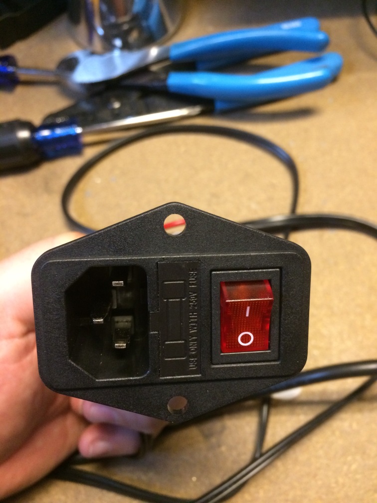
I picked-up a nice power switch/fuse/socket to tidy-up the input side of the power supplies (and make tripping over the cord less disastrous). Also having a fuse is always a good idea.
![2017-04-24 17-54-43 0378]()
About 24 hours later, control panel reassembly begins and touch-up paint is applied. The weather decides to be uncooperative so operations move from the garage to the livingroom.
![2017-04-27 19-34-49 0401]()
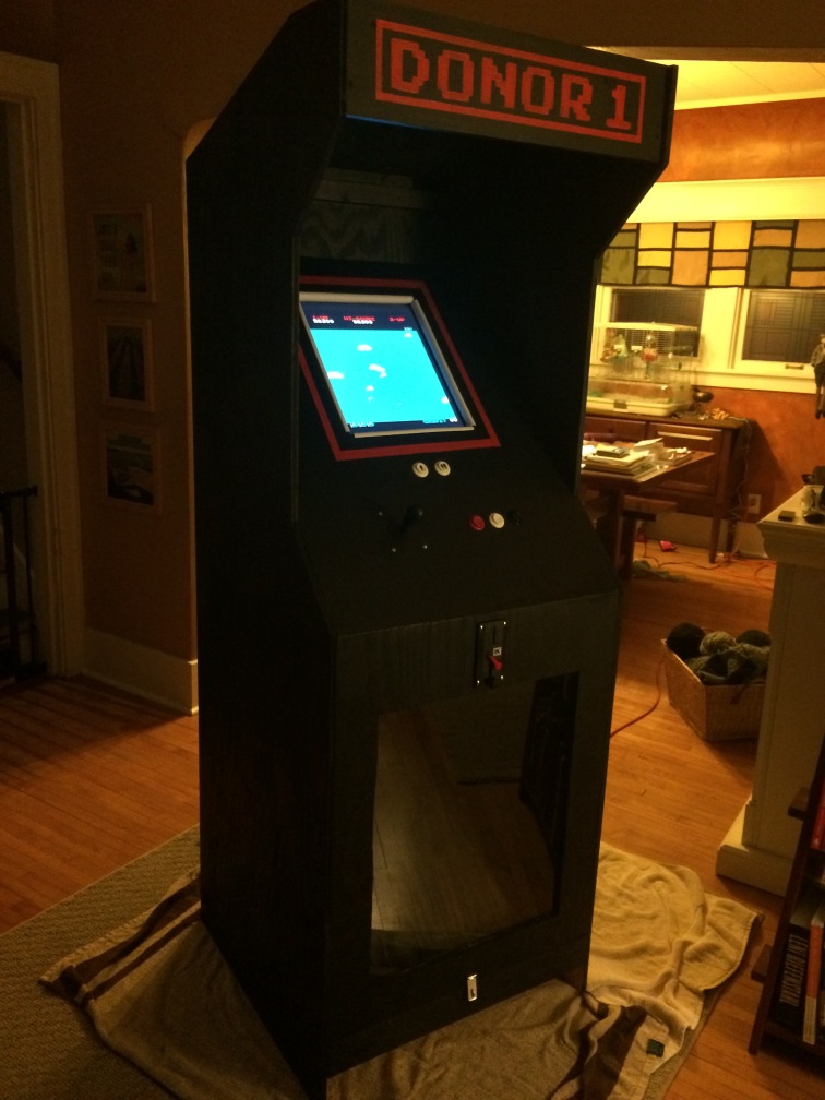
Final assembly commences and breaths are held as power is finally applied. To everyone’s relief, beeps are heard, backlights illuminate and the machine comes alive.
![2017-04-27 20-28-39 0404]()
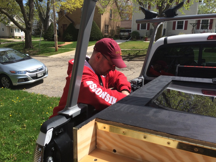
Now that everything is done, the question “how do we get it there?” makes its way to the front of the consciousness. Mike agrees to save the day.
![2017-04-28 11-20-54 0405]()
The next day DONOR 1 makes its way successfully to the venue and to my surprise, weathers the ride with aplomb. A few quick test games with all systems nominal and we put the machine to rest until the following night.
Party Time
![2017-04-29 18-25-18 0411]()
Overall, DONOR-1 faired well and the party was a success. There were no technical problems and we received lots of complements about the machine from players and attendees.
We also spoke to a number of people at the party who inquired about having DONOR-1 raise money for other events. This has been something we’ve wanted to do all along, so it was exciting to hear that there was some interest in putting the machine to work elsewhere (I’ll be sure to post here when it’s going to make another appearance).
What’s Next?
I’ve learned a lot since first putting pencil to paper designing this machine, some of which can be applied to improving DONOR-1 and some that will need to be used in the next iteration of the design. For now we’re discussing how best to share DONOR-1 with others so it can continue to fulfill its mission as a fundraising machine.
The long-term goal is to produce a “reference design” that we could use to create additional machines or could be used by anyone to build their own. Plans like that might take some time to put together (there are a lot of notes to sort through) but in the meantime if you are interested in building a machine like this (or would like to use DONOR-1 as a fundraising tool) get in touch and we’ll share the information we have available even if it’s not in “final draft” form.
Thanks
I want to take a moment to thank the team who made DONOR-1 possible. Given the array of skills needed to come up with the idea and turn my pencil sketch into a working machine on a very aggressive timeline, it would have been impossible to have done it alone (and a lot less fun!).
Thank-you Jamie, Libby, Jim, Patti, Justin, Jameson and Alyssa for all your hard work and patience in making DONOR-1 a reality.
Thank-you Jeff for technical support and input on the electronics, and thanks Mike for coming out on a moments notice to help us get the thing delivered.
I also want to thank Kristin for providing a “totally rad” venue for DONOR-1’s debut, and for enthusiasm and encouragement throughout the project.
-
All Together Now
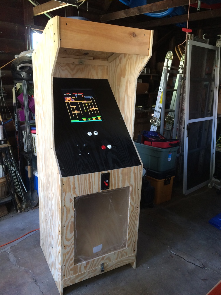
09/06/2017 at 14:08 • 0 commentsLast weekend Ma & Pops brought the cabinet up to the lab, and it looks amazing. Now just screw the control panel to the rest of the cabinet and call it a day, right?
![2017-04-22 08-55-05 0360]()
Not exactly.
This was the first time the control panel would be fit into the cabinet. There’s a lot that could cause this to not go smoothly (small measurement/cutting errors, the dynamic nature of wood, etc.). Surprisingly, the panel slid right in! It was a little snug, but not enough that any changes were necessary.
![2017-04-22 13-37-01 0367]()
Once that was confirmed, the next step was to mount the coin acceptor. I completely underestimated this part of the job.
The first challenge was that I never gave dad the measurements for the coin acceptor (it hadn’t arrived back when I made the original drawings) so it was kind of sheer luck that there was enough room for it between the donations window and the edge of the control panel. Luckily there was enough room, but just barely.
Additionally, the mechanism was designed to be mounted in thin sheet metal, not 1/2″ plywood, so there we had to do a little bit of jigsaw work to get everything to fit and function properly once it was mounted.
![2017-04-22 10-55-48 0363]()
After that things went pretty smoothly. We drilled a temporary hole in the back for the power cords (this will eventually be replaced with a receptacle), ran the power cords, connected the coin slot and screwed-down the control panel.
Last but not least, the trap door on the donation bin needed something to hold itself shut. This isn’t designed to be a high-security machine, so a small lock and hasp was enough to keep anyone from accidentally spilling the collections all over the place.
I have to say it was really cool to see the whole thing together and to play it “at scale”. The dimensions turned out to fit well and the machine is very comfortable (at least for me, maybe for taller people you’d want to set it on a pallet or something). You never know for sure when you start designing something like this how it’s going to feel when it all comes together, and while there are things we’d likely change in the next iteration, overall it’s turned out great, and in such a short amount of time.
![2017-04-22 14-12-55 0369]()
Now it’s time to tear it apart again (or at least remove the electronics) so the rest of the cabinet can be painted. There’s a few other things I’d like to improve (add power receptacle, bigger/better speakers, illuminate the donation bin, tidy-up wiring, etc.) but I think a few more hours of “beta testing” are in order before I dismantle it…
-
Control Panel
09/06/2017 at 14:07 • 0 commentsIn our last installment, dad sent me home with a board that was destined to become a home for the screen, controls and numerous hidden bits of the arcade machine. I call this the “control panel”. Last weekend we had a chance to dig into putting the “control” into the panel…
We’d noodled on a number of layouts for the panel throughout the course of the project. After looking at a lot of existing designs and doing a few “usability tests”, we settled on a fairly basic layout for the controls loosely based on the mid-80’s Nintendo cabinets. This follows angular geometry of the rest of the design (no ergonomic curves here!), and gives us more horizontal room compared to designs that place the player select buttons in the same plane as the rest of the controls.
![2017-04-08 11-13-16 0227]()
Once a layout was decided on, measurements were made and marks were placed. Next comes the cutting, which is of course where things get ugly (because they are less reversible).
I knew that the most challenging part would be cutting the hole for the screen. This would involve a jigsaw, and cutting straight lines with a jigsaw is, in my experience, challenging. Unfortunately, that wasn’t the worst of it. The worst was that I had marked the board on the “inside” of the panel (thinking this would leave the outside cleaner), but on the first cut the saw readily made a mess out of the front of the panel. After this happened, I realized that I already knew that the nicer looking side of the cut is the side the saw is on, but for whatever reason I spaced this and the panel paid the price.
So I knew I needed to make the cuts from the outside face of the panel, but I didn’t want to re-measure everything to transfer all the marks to the other side. I had already made a mistake marking the board earlier and I didn’t want to risk repeating something like that. So, after a little noodling it occurred to me that since everything was either a hole of a straight line, I could just drill small holes through the panel at the various points and then connect the dots!
![2017-04-08 12-37-08 0229]()
This worked well and after a few minutes I had the hole for the screen cut without making too much more of a mess out of the panel. Now it was time for the easy part, the round holes for the controls.
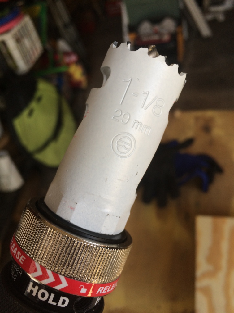
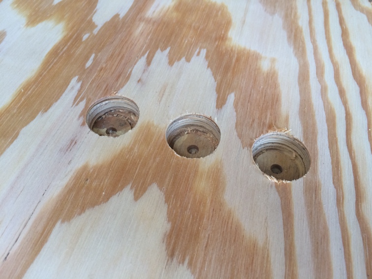
Only this wasn’t so easy. I started with the buttons which are just slightly more than 1″ around. For this I tried using a spade-style drill bit and basically got nowhere. I don’t know if the bit is dull or if it’s just a poor way to cut a hole in plywood but essentially all I got was a nice round indentation in the wood an a little bit of rustic-smelling woodsmoke.
Instead of risking further damage to the panel, I headed to Fleet Farm to pick up a proper hole saw. I came back with a small Milwaukee hole saw kit which included a 1 1/8″ saw which made holes that were almost a perfect fit for the buttons. The kit also included a 1 1/2″ saw that was perfect for making a hole for the joystick.
![2017-04-08 13-21-05 0231]()
The hole saws made short work of getting the controls mounted, and after a little clean-up and sanding, everything fit right into place.
![2017-04-08 13-24-02 0232]()
![2017-04-08 14-10-24 0236]()
After a test fitting, the controls were removed and Jamie spent some time giving the front of the panel a few coats of black paint. Once the paint was dry, the controls went back in and I moved on to the next challenge: attaching the screen.
Beyond cutting a hole for it, I hadn’t given much thought to exactly how I was going to attach the screen to the panel. I had a number of ideas, but now that I could lay the screen on the panel, none of them seemed that great. The biggest concern was that the panel is only 1/2″ thick, so it seemed like it would be hard to fasten anything to the back of the panel without having to pierce the face as well.
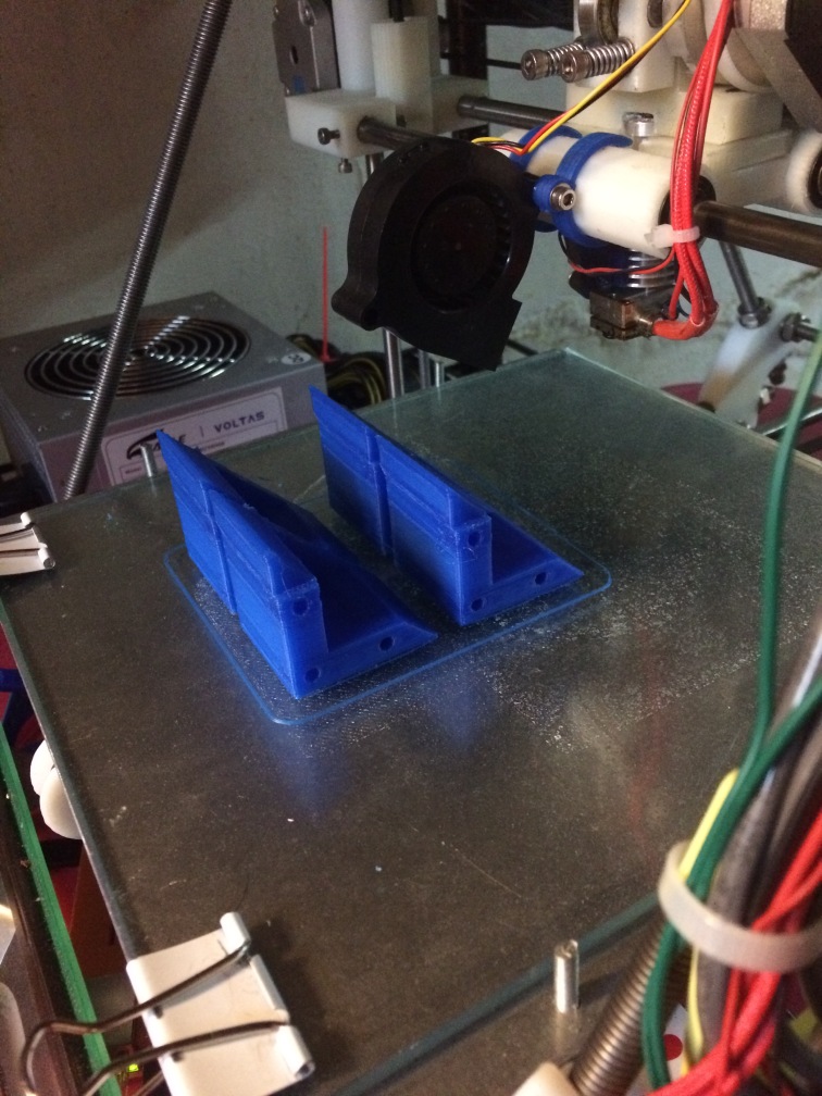
Since it wouldn’t be a GL project if I didn’t find some way to drag 3D printing into it, I decided to experiment with modeling some parts to clamp-down the screen. I still didn’t feel confident that they would be strong enough without going all the way through the panel, but it was worth a try.
![2017-04-08 17-53-21 0240]()
![2017-04-09 07-54-05 0241]()
When I mounted the test part to a piece of scrap panel with three screws I was amazed to find out that not only was it strong enough to hold the screen, but I couldn’t pull it apart if I tried. Those three little screws were able to resist all the pulling and yanking I could manage, so I felt comfortable that four of those clamps could hold the screen in place under reasonable conditions.
![2017-04-09 12-46-57 0250]()
Next I needed to find a way to mount the JAMMA board and its power supply. I knew I wanted to mount the board to the back of the screen, and I imagined creating an adapter that would mate the mounting holes on the JAMMA board to the VESA mounting holes on the screen. However for now I just cheated and lined one of the board’s mounting holes up with one of the VESA mount holes, and then used a self-tapping screw in the opposite hole of the board to thread into a ventilation hole of the screen. This is cheesy, but good enough for testing until I fabricate a proper adapter.
![2017-04-09 12-55-57 0251]()
![2017-04-09 12-56-06 0252]()
Pinning the power supply to the panel was simply a matter of securing the input and output cords using cable clamps. I might do something more sophisticated in the long run but this seems adequate.
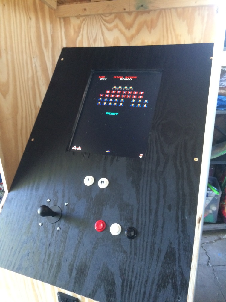
Now that things are tied-down I could start wiring things up to test out the system. Since I had done this once before I didn’t expect any surprises, but I did notice one small problem when I booted the system up the first time.
![2017-04-09 13-02-46 0255]()
Fortunately this was easily remedied by flipping a configuration DIP switch on the JAMMA board, as flipping the screen physically would have caused some alignment problems. Once this was resolved, I tied a temporary speaker to the wiring harness and the system was ready for testing.
![2017-04-09 14-32-17 0267]()
Overall everything held-up and worked as expected. It’s a bit awkward to work with the panel outside of the rest of the cabinet, but overall the system performs very well. There is some additional clean-up work to do with the wiring, and I still need to test connecting the coin acceptor, but for the most part the electronics aspect of the project is complete.
While we were working on the control panel, mom, dad and my “little” brother have been banging-away at the rest of the cabinet. I got a glimpse of their progress a few days later through some photos they posted.


Things are really starting to take shape and I’m very excited to get together with dad again and fit the control panel to the rest of the cabinet. I have a few other “nice to have” features planned for the machine, which I might dig into between now and the next time we can work together, but even if those parts don’t turn out, it’s looking like we will have a working machine in time for the fundraiser.
-
Cabinet
09/06/2017 at 14:05 • 0 commentsLast weekend dad and I started working on the cabinet. I wanted to take more pictures, but it’s tricky to document and get this kind of work done at the same time.
The design is based on a combination of the original Pacman cabinet crossed with a Space Invaders cabinet. I liked the Pacman designs simplicity of mounting the controls and screen in a single panel but I also liked the more angular outline of the Space Invaders cabinet (felt more 80’s to me than Pacman’s curves). I sketched this up a few times and once I had something with a few measurements in it I passed the drawing along to dad who ran with it and turned it into something with enough information to actually build something from.
![2017-03-25 10-45-03 0134]() Dad with the full-size mock-up (the perspective makes it look a bit smaller than in person)
Dad with the full-size mock-up (the perspective makes it look a bit smaller than in person)The cabinet design has a few other considerations that might not matter if you’re building one for personal use, but were important for the Charity Arcade machine. First is the transparent “coin case” that displays the donations and second is that it needs to be portable enough that Jamie & I can get it around. In our case this means light enough for two to carry it and small enough to fit into the back of our Honda Element. After a few phone calls and emails dad tweaked the design to meet these requirements and made a few improvements as well.
A lot of the time was spent confirming the design and measuring the “fixed” components of the machine (the screen, controls, other electronics, etc.) as well as validating the basic measurements for usability and portability. Once that was done, we could start making some cuts.
![2017-03-25 11-39-24 0138]() Partial cardboard mock-up of the control panel
Partial cardboard mock-up of the control panelThe design is intended to make use of two 4×8′ sheets of 1/2″ plywood, so the first cuts were to get the sheets down to a more manageable size.
The other priority was to get the “control panel” cut so I could take it back to the lab and install the electronics. Getting the angles just right was a bit of work due to the size (it wouldn’t fit on the radial arm saw, etc.) so we ended up freehanding it with a circular saw, but it turned out just right.
![2017-03-25 13-02-33 0140]() The “uncarved block”…
The “uncarved block”…It was really cool to start seeing the parts take shape. It’s easy to get focused on the goal at this point but there’s still a lot of work to do and I don’t want to miss out on the joy of building the machine by focusing on having it done. Next step for me is to layout all the electronics on the control panel, cut some holes and see how it all fits together. In the meantime dad’s going to keep working on the cabinet and we’ll get together and compare progress again soon.
-
Electronics
09/06/2017 at 14:04 • 0 commentsWhile the electronics are off-the-shelf, the documentation available is not exactly straightforward. Here’s what I’ve been able to decipher so far.
![2017-03-22 19-49-04 0128]()
The 60-in-1 board uses the standard JAMMA connector, however it also includes a few modern connectors as well:
- A VGA video connector
- A Molex power connector
- An 1/8″ stereo audio jack
- 2 Mystery connectors
I struggled a bit to get a handle on what the power supply requirements are for the JAMMA board. After a number of conversations (and a lot of web searches) I found out that the Molex connector is exactly what it looks like; a standard PC-style power supply input.
Of course I had already bought the wrong supply before finding this out.
For some reason, I thought the JAMMA board only needed a 5VDC supply. This was a drag because I later found out that the coin slot I bought needs a 12VDC supply. Turns out the JAMMA board needs both 5VDC and 12VDC. The up side is that when I have the right supply for the JAMMA board I’ll have everything I need for the coin slot…
I talked to my friend Jeff about this (he’s built one of these cabinets before) and he said that he just used an external hard disk power supply. I did some digging and found something like this in the parts bin and sure enough I had one already.
I wired-up up the power supply via the JAMMA wiring harness because I knew I would need a 12VDC supply for the coin slot. Later (after talking to Jeff again) I found out that there are 12VDC supplies coming off the JAMMA connector to power things like the coin slot, so it makes more sense to connect the power supply to the Molex connector and then feed the rest of the system from the wiring harness.
After noticing that the wires in the harness are bundled into groups that lead to the sections of the cabinet (the player controls, the coin box, etc.), it wasn’t too hard to trace the wires from the board to to figure out where to hook-up the joystick, start buttons, speaker, etc.
With the basics wired-up I applied power to the board and it didn’t start on fire!
![2017-03-22 19-48-56 0127]()
I spent some time figuring out how to access the settings and configure the board as well as navigate around the game selection interface. We played a couple games of Ms. Pacman just to make sure everything was working properly.
![2017-03-22 20-33-39 0130]()
The goal of all this was to make sure the parts would work together and nothing was DOA with enough time before the deadline to order any replacements. Everything other than the coin slot tested out (I kind of forgot to try hooking it up). I labeled all the wires and tied things up with zip-ties so I won’t need the entire dining room table to hook it up next time, and through the process learned a number of ways to improve how things should be connected.
There’s a few more things I want to test out with the electronics, and I have some more parts on-order that I’ll need to incorporate if they show up in time. In particular, I want to have a display which shows the total amount of donations collected. This will use an LED matrix installed in the “marquee” part of the cabinet, and use an Arduino (or perhaps an ATTiny ) to drive the display. I also want to add some illumination to the coin collection bin, perhaps controlled by the same brain as the LED matrix. We’ll see.
Next time I’ll be diving into building the cabinet with my father. This is the part I’m most anxious about because I have a lot less experience with woodworking than I do with electronics. Fortunately my father has a lot more experience with this than I do, so I’m looking forward to diving into that with him.


 Dad with the full-size mock-up (the perspective makes it look a bit smaller than in person)
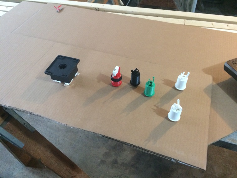 Partial cardboard mock-up of the control panel
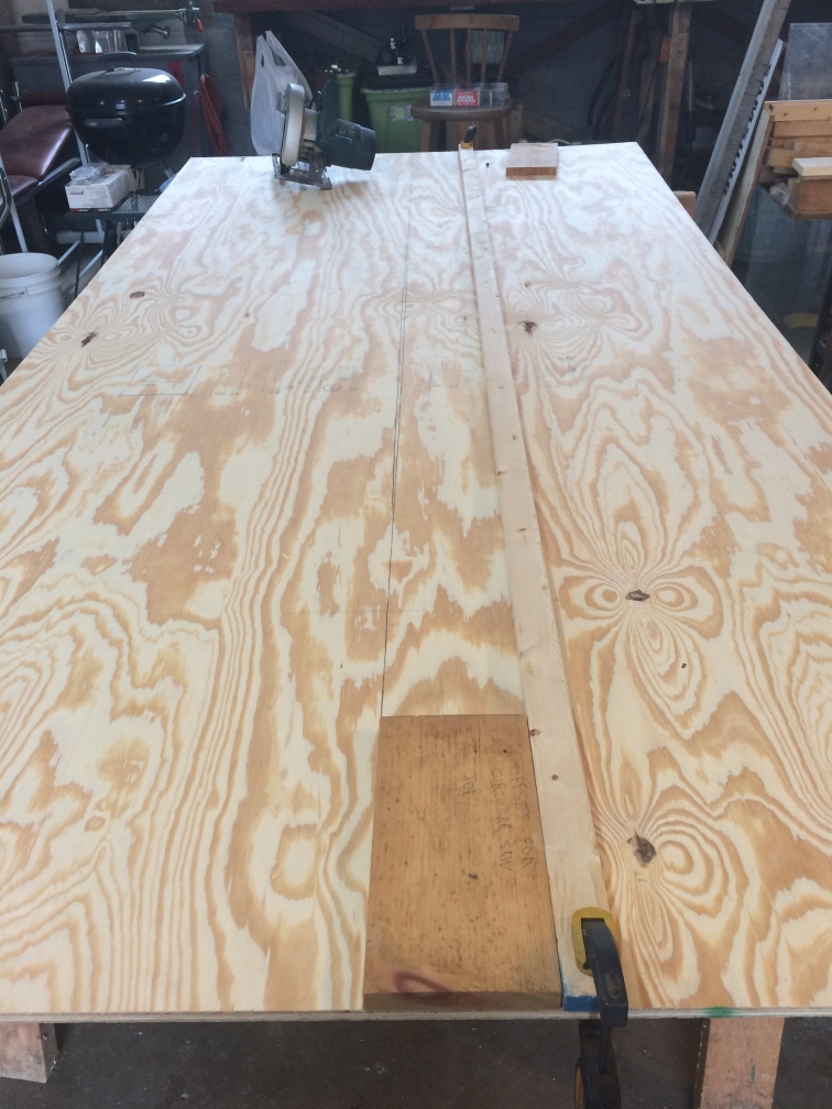 The “uncarved block”…

