 x-labz
Block diagram
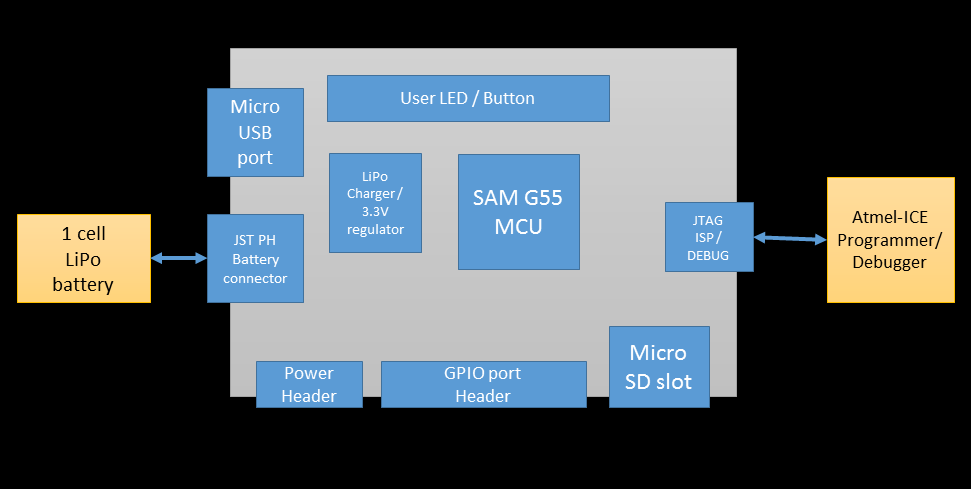
Features
- SAM G55 MCU with FPU @ 120MHz ( 512 Kbytes Flash / 176 Kbytes SRAM )
- ARM Cortex M4F core
- JTAG ISP / Debug port ( external programmer / debugger needed )
- micro USB port for communication and battery charging
- LiPo connector and charger
- 3.3V / 1A switching regulator ( ...to feed the external peripherals )
- 32.768 kHz crystal
- User button and LED
- Reset button
- Micro SD card slot ( SPI )
- GPIO port header
- Extra power header for the external peripherals


 Ward Almasarani
 SeanEE
 Yerkebulan
 Nathan
I want an easy way to test the product after it is assembled and NOT have assembly technicians use a debugger on the assembly line. Inserting a USB cable and looking for a CR response (as with SAM-BA) is easy to do with the Atmel E70. Don't know why Atmel didn't add USB to the bootloader code! Also the 10 pin SWD connector adds cost when already have USB!
Hope you add the schematic soon. Need to see if I am on the right track! Thanks!