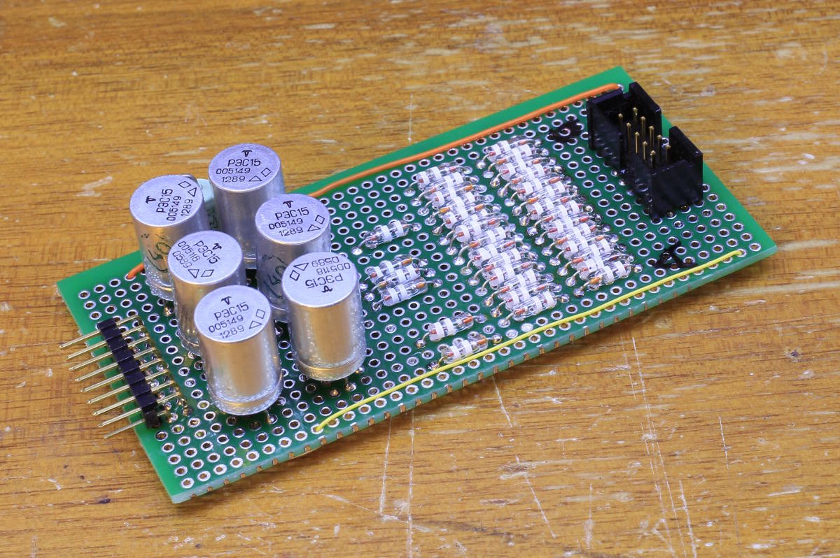
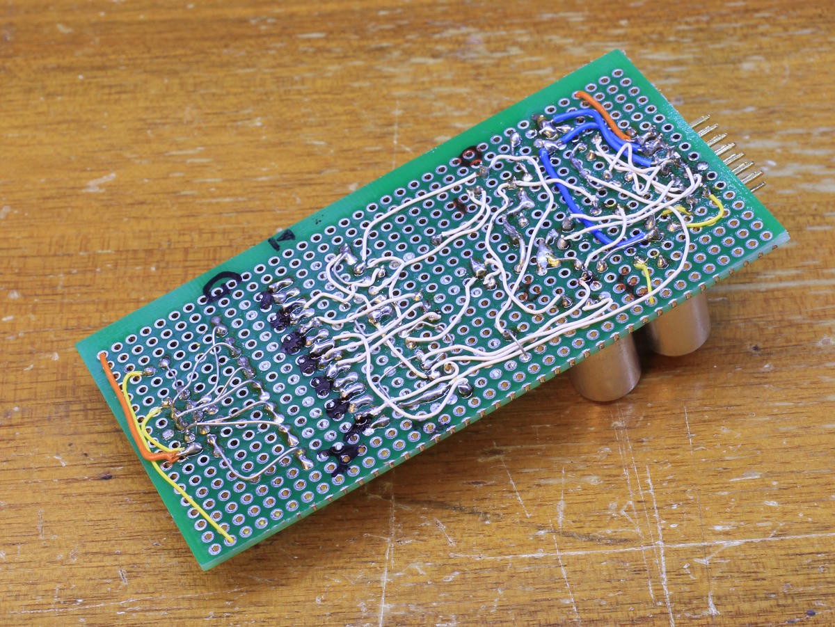
This other module is now OK as well !
What a mess... There were a number of blunders but I managed to find and correct them all.

The component side is nice but the wire side is ... less nice.

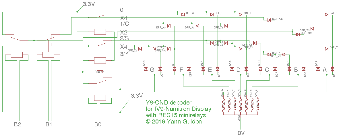
I somehow managed to swap and invert some signals so it is not an exact copy of the schematics (shown below again for reference)

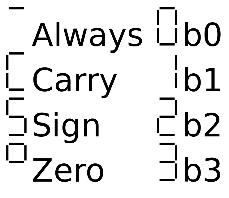
This circuit decodes 3 input bits to the following symbols on 7 segments :
A 4th bit is inverted with a relay to drive a small Glühbirnchen and signal inversion. Maybe I should also output the "NEVER" condition on the last signal of the connector...
The system is shown and operated in this short video :
I hope you enjoy hearing the relays' clicks :-)
Update :
I also added an auxiliary output to help signal the "NEVER" condition.
However the polarity is inverse (compared to the hexadecimal modules) and can't be displayed on the usual test module.
A reversed diode and a Glühbirnchen are enough but I'll see later how to better exploit this signal (in conjunction with the 4th "neg" bit).
 Yann Guidon / YGDES
Discussions
Become a Hackaday.io Member
Create an account to leave a comment. Already have an account? Log In.