 Yann Guidon / YGDES
In the Y8, instructions come :
- from the program memory / PROM
- from the assembly panel
- from eventual "modern" sources
Then the instruction bits are amplified, eventually latched, and sent to :
- the processor's instruction decoder
- the disassembly panel
- eventually something else such as a semiconductor device...
This is a bit more complex than just plugging things together because all the electrical signals must be at the proper levels...
For now I have built the assembler panel and I start building the disassembler, and I'd love to test them together, but the levels are not compatible :
- The input is a low-current (2mA), medium voltage (about 6V) signal
- The output must be able to drive a string of RES15 coils (50 to 60mA max)
The RES64A is appropriate to buffer the signals and even latch them, if appropriate biasing is enabled.
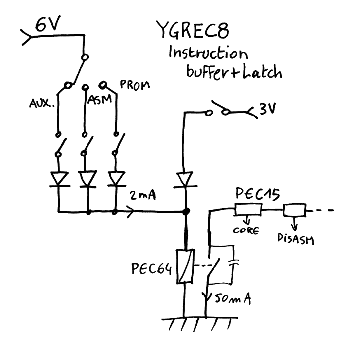
The latch feature can be enabled on demand, for example during sensitive phases of the instruction cycle.
Another row of relays can also (dis)connect the RES64's coil from the input, to freeze the state of the processor while the memory and other circuits are in transient phases. The RES60 would be appropriate because it's small and DPDT so only 8 relays are needed, which uses much less room than the other methods. The 16× RES64 will use quite a lot of room, in comparison...
For convenience the latch doesn't use an intermediary capacitor because some operations require a direct connection to the core.
Now I have to find a PCB that can host 16× RES64...
20191118: I drop the idea of the RES60 latches because there must be a proper "instruction register". Program memory can also contain data that must be read by LDCL/LDCH and an early latch would make it harder later...
It also saves some of these precious relays.
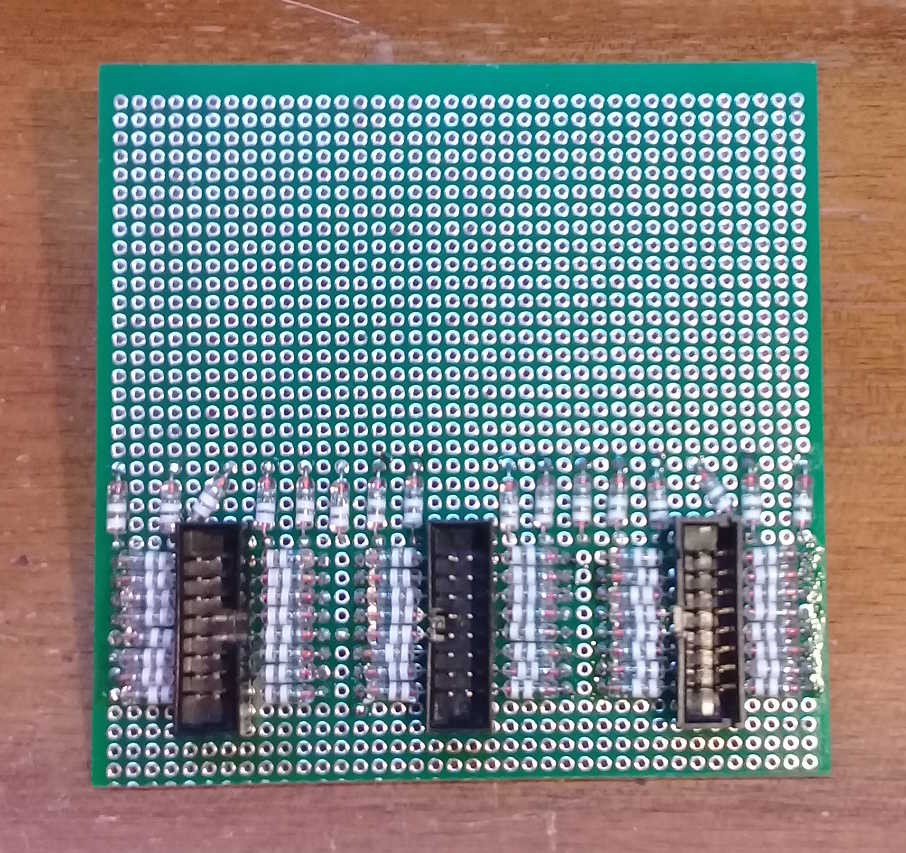
So I started building the hub board on a smaller board, with only 3 connectors and their 48 diodes. More diodes provide the latching for the RES64. The relays will not be placed yet because I need to bin/sort the whole lot and I have not received everything yet. The preliminary data is in the log First plots.
The relays will be placed on staggered positions on both sides of the board to save space, just like it will be for the register set.
Hopefully I'll have some room left in the corners for mounting holes...
Discussions
Become a Hackaday.io Member
Create an account to leave a comment. Already have an account? Log In.