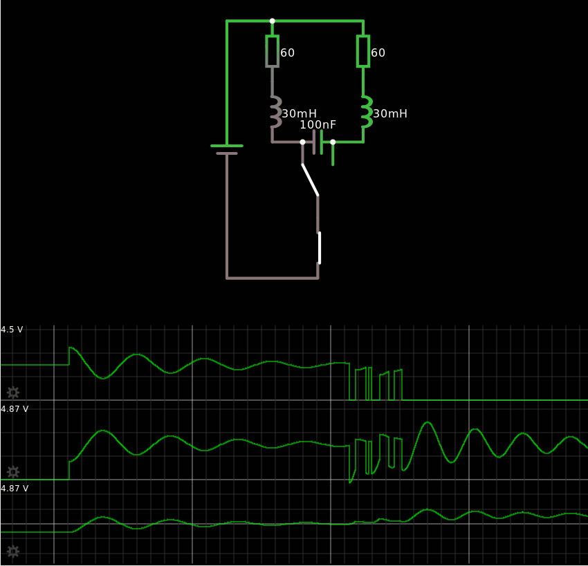
As you might already know, if you have followed the #YGREC16 - YG's 16bits Relay Electric Computer 's saga, one of the challenges with relays such as those I use is : fanout. These relays have a relatively poor current amplification capability : the coil is rated at about 60mA and they can switch maybe 2× that value. So when I have to distribute a signal to many other relays, I have to:
- connect the relays in series, so the voltage increases instead of the current
- be smart (that's how I came up with the balanced control binary trees).
- use hysteretic mode (CC-PBRL) to reduce both the voltage and current.
The hysteretic mode is a pretty smart circuit that is more energy-efficient than plan on-off switching. However it suffers from a very practical effect : as the circuit functions, its coils resistance dissipates the power and heats. This heat in turn changes the resistance of the coil, as well as the current, and the working point of the system. Some adujstable resistors are required to finely tune the operating point and the system might behave differently depending on the environment and temperature.
The circuit I explore here is an interesting alternative because it avoids some problems from the CC-PBRL circuit :
- no more alternate supply rails (caused by the polarised capacitor)
- no more temperature sensitivity
- no freewheeling diode
- no large non-polarized capacitor
- current draw is 1/2 of full power and does not vary significantly (it's roughly as efficient as CCPBRL)
The last part is important : power consumption is a problem that directly affects the power supply's design, and I'll use "basic" circuits with transformer/diodes/filtering capacitors. Their values determine the weight, cost, size etc. of the system.
The first trick (again borrowed from ECL circuits) is to always have one half of the relays powered : this effectively limits the maximum power requirement. The control relay can switch from one half to another and each contact has an equal wear. The power is interrupted only during the short time when the relay's contact is not connected to either branch. This is only a few ms at most, which is easy to filter on the power supply. Slave relays can be connected in series, as many as required.
But switching noise is annoying, particularly when countless coils are charged and released, their 30000µH can store quite a lot of energy. So the surges must be avoided when one branch is disconnected. Usually, diodes are the default choice but it's not satisfying. I want the excess energy to be recycled and start to energise the other branch...

The solution is a simple capacitor across the control relay's pins. The above picture shows a simulation with Falstad where I try to simulate the behaviour using realistic values. Here is the code if you want to try at home:
$ 1 0.000005 0.10425469051899915 50 5 43
c 352 256 320 256 0 1e-7 -3.3621449028580765
v 240 400 240 128 0 0 40 3 0 0 0.5
l 288 192 288 256 0 0.03 -0.0006352952130544926
r 288 192 288 128 0 60
S 336 336 336 256 0 1 false 0 2
r 384 192 384 128 0 60
l 384 192 384 256 0 0.03 0.04897750082379863
w 288 256 320 256 0
w 352 256 384 256 0
w 240 400 336 400 0
w 240 128 288 128 0
w 288 128 384 128 0
s 336 336 336 400 0 0 false
o 7 1 0 4098 6.0193733601080295 0.0001 0 2 7 3
o 8 1 0 4098 6.00000000171388 0.0001 0 2 8 3
o 0 1 0 4098 6.000000000002793 0.0001 0 2 0 3
o 10 1 0 4609 5 0.1 0 2 10 3
38 0 0 0.000001 0.000101 Capacitance
With this simulation, I found that the size of the capacitor was not as I expected, and a classic ceramic 100nF is enough : the current in the coils varies slowly because of the very high inductance. And there is no high voltage spike to filter out ! The capacitor must be unpolarised but can be a reasonably low value (2×PSU provides a great margin).
I also simulated the current during switching :

The supplied current (yellow trace at the bottom) drops immediately (this must be filtered on the power supply) but the current increases slowly (approximately 1ms). A hysteretic circuit would not interrupt the power at all but there would be short spikes from the control signal.
There are unavoidable oscillations but they are limited to a closed circuit inside the loop that is closed by the capacitor. The frequency is determined by the values of the inductors and capacitor and I find approx. 3KHz with 100nF and 30mH. Yep, it makes sense :-D 330nF would give 1KHz.
I have published this circuit in September in GNU/Linux Magazine France but hadn't simulated it yet. Now I have a better understanding of the parameter, I was mostly concerned about the capacitors's value. I'll have to implement it and compare with the simulations !
 Yann Guidon / YGDES
Discussions
Become a Hackaday.io Member
Create an account to leave a comment. Already have an account? Log In.