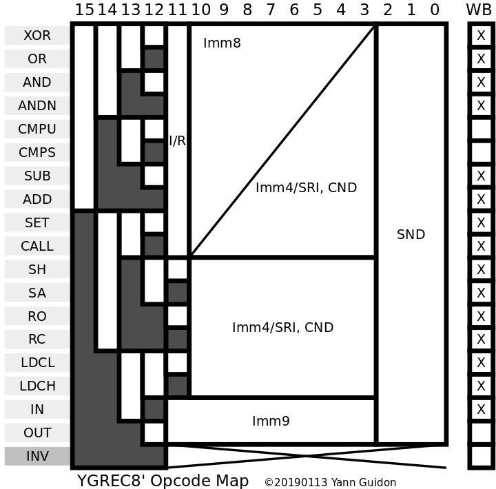
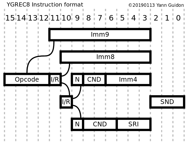
You modify a detail and all the rest crumbles. So after a few "modified details" added up, I had to take a global view again. Here is the result:

I did my best to avoid fragmentation, while keeping most of the constraints already established. For example, XOR and SET/CALL differ with the bit 15. The first half (8 opcodes) has not changed, but I have moved all the others : SET/CALL are now situated just after the ALU operations, instead of at the very end. The SHL (Shift/Rotate) unit comes next, without Imm8. LDCx also has no Imm8, followed by IN/OUT using only Imm9.
This hopefully simplifies the assembler (which must be rewritten) as well as the instruction decoder (fewer gates).

SND has been moved to the LSB because it looks simpler this way (what do you think ?). This probably amounts to half of the modifications to apply to files and documentation... and also source code because now SND is at the last position !
 Yann Guidon / YGDES
Discussions
Become a Hackaday.io Member
Create an account to leave a comment. Already have an account? Log In.
no NOP or HALT op codes, what is your reasoning on those?
Are you sure? yes | no
NOP is a special case of "XOR never", encoded as 0000h (the "never" condition is available for the first 10 opcodes anyway)
HALT is a special case of "CALL FFh PC" (it will loop or reboot, depending on what is at instruction at address FFh)
Are you sure? yes | no
As I somehow managed to get one free opcode, it was allocated INV, encoded as FFFFh (the value of a blank (E)(E)PROM cell). It was previously congruent with HALT but the separate semantics allows more freedom of expansion if one or two small opcodes are added, and eventually emulated (though the "overlay" mechanism allows quite a few things already).
At this moment I am rewriting the assembler, which should be easier thanks to the better opcode organisation :-)
Are you sure? yes | no
Hi Yann, if you want to have an easy to understand hex form of your output (or do you want to go octal?), it would be nicer to put the instruction bits in another order, for instance:
Imm8 case:
4 bits opcode
4 bits (I/R bit and 3 SND bits)
8 bits immediate
Imm4 case:
4 bits opcode
4 bits (I/R bit and 3 SND bits)
4 bits (second I/R, N, and 2bit CND)
4 bits immediate
With this organization, it is much more easy to recognize the components of your instruction when you see the hex representation.
Are you sure? yes | no
earlier, SND+I/R was between the opcode and Imm8 but the Imm9 field and the 5-bits opcode fields were not contiguous, it created a few wrinkles...
Reading the instruction in hexa/octal directly is not really a concern because the "hardware assembler/disassembler" will decode the fields easily :-)
Are you sure? yes | no