 Yann Guidon / YGDES
20200810: see 122. Updated Gray Counter for the rest of the story !
I must make a Gray code counter !
It is not obvious why but it's an important piece of circuitry that is required by the debug/test port... Have a look there for some background :
4. The YGREC debug system
16. Inspect and control the core
24. Synchronous Serial Debugging
That should cover the bases, right ?
Of course I could still use a natural binary counter and XOR the consecutive outputs but that would be rather heavy, considering that there are already a XOR for each bit (plus the carry tree).
The constraints are :
- simple and regular structure to ease P&R with copy-pastes
- fewest gates
- glitch-free outputs (or else, I'd use a simple ripple counter)
- speed is not critical so ripple operation is OK
- There is no need of a specific Gray code, variations are not a problem as long as all the codes are covered.
So let's get started.
The easiest and smallest Gray counter is just a pair of D flip-flops.
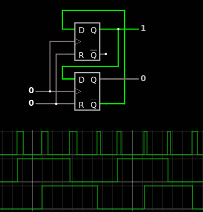
This won't go far, as I need 6 bits. Then why not cascade them ?
Looking at Gray sequences, it appears that the above circuit goes 0-1-3-2 then 2-3-1-0. The codes 0 and 2 are consecutive, which complicates things a bit, but let's now look at how to reverse the sequence.
The sequence direction is easily changed by XORing one of the outputs.
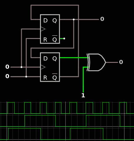
but this creates a glitch.
This glitch could be avoided with the XOR inside the feedback loop, such as :
but we get a different effect : this XOR inhibits the counter (when both outputs are the same). This is not a success but not a failure either, since this can be useful later !
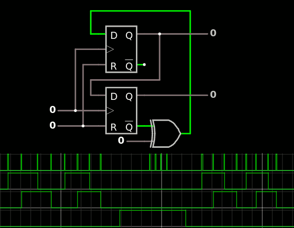
What is missing is a 2nd XOR :

(note : this Johnson counter can change direction so easily because there are only 2 DFF. With a 3rd DFF it becomes too complex).
.
Fun fact : if you have complementary outputs available, you can replace the XOR with multiplexers.
.
But now we have to alternate from one direction to the other. This implies a 3rd DFF that holds the "direction" level (for now) and some decoding logic.
For now, we'll just simulate the DFF with an up/down switch, and add a couple of gates to "saturate" the counter :
- in the 2 state in the Up direction
- in the 0 state in the Down direction.
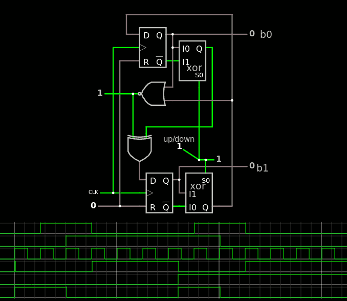
This is necessary because these states are "repeated", once before and once after the transition of the more significant bit.
So far, 3×XOR and 1×NOR.
Then, it's just a matter of connecting the new FF to the NOR that sends a pulse when 0 or 2 are encountered in the right context. Et voilà !
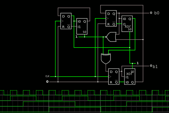
The 5 gates on the right have the following ports :
- RESET input
- Clk input
- DIR input
- OV output
- b0 and b1 outputs
If all you want is 3 bits, that's fine. A few things can be simplified but these are only details. The trick now is to make it modular...
The next step substitutes the single DFF with the other stage.
Here is the new circuit : a 4-bits Gray code generator !

There are 2 things to consider :
- The b2 output doesn't toggle correctly and can't be fed to the LSB block so the 2 MSB are XORed to give the proper direction.
- The FF must have an "enable" input to select when to change the value. This is emulated with the MUX2 in front of the MSB DFF because Fasltad's circuijs doesn't have that sort of gate (or an extensive library either).
The Critical Datapath is 3×XORs and 1×NOR. I'm not aiming at lightning speed anyway.
That's 4 bits now. From there the rest is easy...
To complete the missing bits, another stage is inserted in the middle, reusing all the methods described above. The circuit is epic !
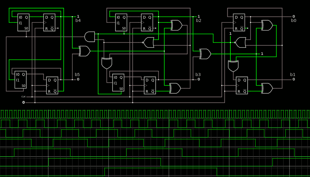
I notice that the system is not perfect yet. The codes are running almost right, as I see some clock cycles are skipped... I'm almost there !
The solution is to rewire one XOR gate to correctly propagate the "direction" signal:
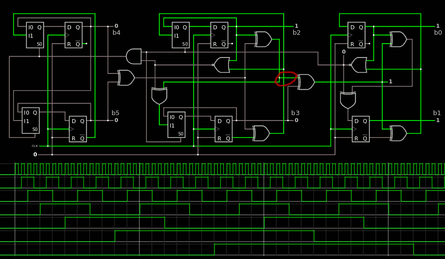
There !
The system is glitchless and modular : it can be expanded to any size, with the LSB, "middle" bits and final circuit with 1 or 2 bits). The CDP is not wonderful (5×XOR: not surprising) but this is not a practical problem in this precise application.
The circuit contains :
- 6 DFF
- 8 XOR2 and 3 other boolean gates
- 4 MUX2 (might be merged into some DFF
And now... VHDL.
20200720 : the source code is now in VHDL/TAP/Gray and works well. It uncovered a really stupid bug in the VHDL gates library which is now solved, and the Gray counters are now also part of the regression tests.
20200808 :
The Gray code is validated in synthesis with Synplify & Libero SOC. However, the circuit must evolve because I'm redesigning the TAP to share the Gray counter with more circuits ! See the log 120. TAP v.2
Discussions
Become a Hackaday.io Member
Create an account to leave a comment. Already have an account? Log In.
It is cool to watch you work out the issues. I just smack my head into a wall and then keep on hitting it ;-)
Are you sure? yes | no
keep your head cool and just click on the falstad links for more fun ;-)
Are you sure? yes | no