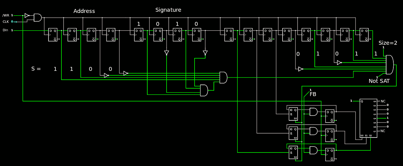
As shown in the log 111. Design of a TAP : the SIPO Controller, the first module is the "selector", used by the other modules to enable a given sub-chain or another, or none (when the "null" command is given).
A preliminary version is simulated in Falstad :

This module provides both an early signature decoder, as well as the SIPO chain for the first 16 bits, available to other modules.
The latching mechanism is also specific, unlike the latches of the other modules : if the FB (Full Byte) signal is off, then the selector register is cleared when /WR goes high. This catches most of the wrong sizes, including NULL, to prevent unwanted spurious behaviours.
The 3 cells can be replicated as needed if more outputs are required but 8 is already enough for a small circuit like the Y8. The codes 000 and 111 are avoided to further prevent spurious operations. The cell structure is unusual : a AND is inserted between the loopback MUX and the DFF, which has no /RESET input (just send an invalid command to clear). This system is fully synchronous, using 2 non-onverlapping clocks (CLK and /WR must be kept separate by the host)
Another subtlety : this module has a "permanent" output that must remain valid after more than one command, and it must be cleared by invalid commands so a DFF is used, instead of a latch. /WR is not used by the decoding logic, but other simpler modules will use latches and /WR must be decoded.
The TAP is looking better each day...
20200728 : I changed the command prefix to match the ASCII 0-7 characters :-)
 Yann Guidon / YGDES
Discussions
Become a Hackaday.io Member
Create an account to leave a comment. Already have an account? Log In.