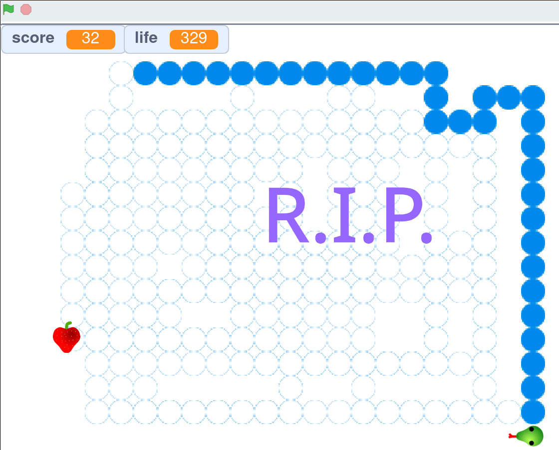
For this 150th log, the new assembler lets us put everything together and consider a larger program than the short examples we've seen so far. So it's time to implement this Snake game, at last!
But it's also a sort of "code golf" for two reasons:
- there is not much space for code and data
- the code is expected to run on a very slow machine (the relay-based one, not onlu the FPGA)
The relay machine is expected to reach maybe 20 to 30 IPS (instructions per second, yes) which leaves no headroom at all for a game loop, 20 instructions per loop for a 1Hz refresh rate. So that's maybe 30, maximum 64 instructions to store (or program on DIP switches). Yet the YGREC8 is not designed for the Ultimate Code Compactness of All.
The first thing to determine is the direction. Already it becomes clear that the constraint of keeping the shortest possible execution time requires 4 separate code paths, otherwise there are many redundant or useless tests. So some duplication will appear but I don't think the size overhead will be significant, because there is more to do than steer the worm.
Another part is about "drawing the snake". This is common with the 4 code paths. This can be reduced to two steps :
- draw the head
- erase the tail
The head's new coordinates are given by the 4-parallel codepath discussed above. Removing the tail though requires storing the coordinates of all the X×Y previous positions, since eventually the snake could fill the whole screen. The required storage space gets too large. But there is a trick: the snake can only move to one of the 4 adjacent locations. This can be encoded in 2 bits.
Managing the scoreboard is another task to consider. Managing the counters and updating the display will take "some cycles" for every iteration. I know because some time ago, I did this:

so some of the game mechanics is already conceptualised, except that here, the playground will be "black or white" dots. Or yellow, in the case of my flip dots.
I don't know how many dots there will be but likely more than 16×16 and dot coordinates do not fit in a byte.
The interface also includes 5 buttons (up, right, down, left, start/stop) and some sound (let's say the electromechanical chime)
I explored the technical details at https://hackaday.io/project/20864-ygrec-15-bis/log/57054-tubular-bell.
For the 5 buttons, let's simply say their state can be read directly off a GPIO port, mapped in the IO register space. Or, to make it even more handy, map the 4 direction buttons to the B0, B1, B2 and B3 conditions! The 4 buttons must first have a priority encoder then "remembers" the last choice, in case nothing is pressed. The "choice" can be stored as the address of one of the 4 direction handlers.
The trick here is to use an address register to index the table of entry points, save the index when a choice is taken, and restore the last valid index in case no new choice appears.
; First draft for the direction decoder

; in bank 1:
.EQU jump_table 1
; indices 1 to 4 store the values of Top_Handler,
; Right_Handler, Bottom_Handler and Left_Handler

; in Bank 2 :
.EQU last_choice 1

.ORG 0
; init the jump table
set jump_table A1
set Top_Handler D1
add 1 A1
set Right_Handler D1
add 1 A1
set Bottom_Handler D1
add 1 A1
set Left_Handler D1

set last_choice A2
set Right_Handler D2

;; ...

Top_Handler:
  set D1 D2 ; save the choice
  ; ...
  set Select_direction PC ; or somewhere else

Right_Handler:
  set D1 D2 ; save the choice
  ; ...
  set Select_direction PC ; or somewhere else

Bottom_Handler:
  set D1 D2 ; save the choice
  ; ...
  set Select_direction PC

Left_Handler:
  set D1 D2 ; save the choice
  ; ...
  set Select_direction PC

; ....

Select_direction:
  set last_choice A2
  set jump_table A1
  set D1 PC IF0
  add 1 A1
  set D1 PC IF1
  add 1 A1
  set D1 PC IF2
  add 1 A1
  set D1 PC IF3
  set D2 PC ; default/old value
The priority encoder/dispatcher uses 10 instructions, plus one in each branch. A smaller/faster dispatcher could use a table of precomputed indices, indexed by the value from the IO space. The total space would be 16 instructions, which is almost equivalent to the initialisation code and dispatching segment.
set last_choice A2
in buttons R1 ; read the external state
and 15 R1 ; mask only the relevant buttons
set D2 PC IFZ ; jump to last choice if no button
add (jump_table-1) R1
LDCL R1 PC ; lookup and jump

jump_table:
; .DW 0 ; 0000  => handled by the dispatcher
.DW Top_Handler     ; 0001
.DW Right_Handler   ; 0010
.DW Top_Handler     ; 0011
.DW Bottom_Handler  ; 0100
.DW Top_Handler     ; 0101
.DW Right_Handler   ; 0110
.DW Top_Handler     ; 0111
.DW Left_Handler    ; 1000
.DW Top_Handler     ; 1001
.DW Right_Handler   ; 1010
.DW Top_Handler     ; 1011
.DW Bottom_Handler  ; 1100
.DW Top_Handler     ; 1101
.DW Right_Handler   ; 1110
.DW Top_Handler     ; 1111
The 4 handlers don't change, and it takes only 4 instructions to handle the default codepath instead of 10 now. This is where orthogonality shines, as it allows the combination of several functions in one instruction.
 Yann Guidon / YGDES
Discussions
Become a Hackaday.io Member
Create an account to leave a comment. Already have an account? Log In.