 Maria Carlina Hernandez
-
1Wiring and Casing
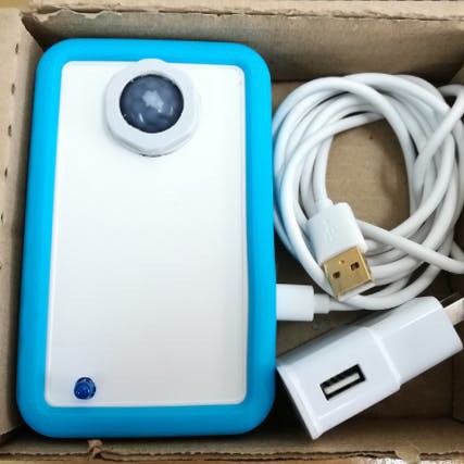
As you can see, the motion sensor has three pins: V+, Ground, and a third for outputs signal ("1" = movement, and "0" static environment). First plug the cables straight to the pins of your NodeMCU, follow the table and diagram below:
NodeMCU -> PIR Sensor - NodeMCU -> LED
GND -> GND - GND -> GND
D6 -> OUT - D4 -> VCC
3.3V -> VCC - - - - - - - -
Because the sensor is very sensitive to movement, I used the jumper switch behind it to set the lowest sensibility. I also painted over the lense corners to focus on one specific space instead of omnidirectional. (This was for my liking, but please explore and innovate as you see fit) The results of these few extra minutes of work result in the a friendly, contained device.
![]()
-
2With the case and and device pieced together, we now need to connect with Arduino IDE
To start, connect your NodeMCU to your computers port using the micro USB
Note: If you do not already have the Arduino IDE, click here to download.
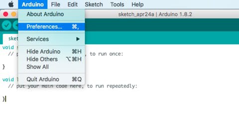
1.- Open the Arduino IDE, select Files -> Preferences. >Next input the following URL into the Additional Board Manager URLs text box. You can add multiple URLs, separating them with commas if needed.
http://arduino.esp8266.com/stable/package_esp8266com_index.json
NOTE: If you're a Mac user, please note that Arduino and File contain different drop down functions compared to Windows operating systems. Also, you will need to install the following driver to be able to upload your NodeMCU.
![]()
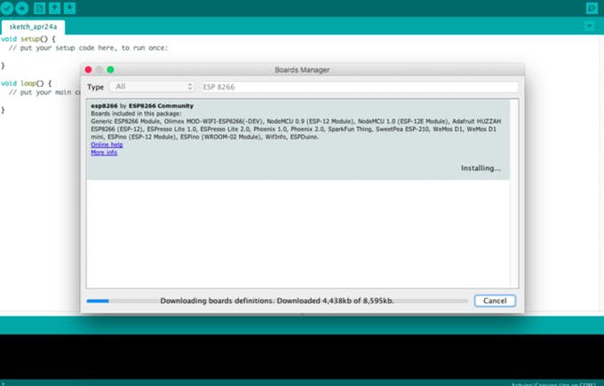
2.- Open Boards Manager from Tools -> Board menu and install ESP8266 platform. To simply find the correct device, search ESP8266 within the search bar.
![]()
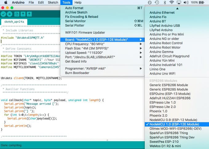
3.- Select your NodeMCU 1.0 (ESP-12 Module) from Tools > Board menu.
![]()
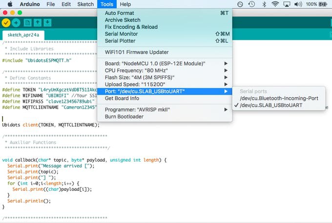
Additionally, we need to be able to communicate with the NodeMCU, we also need to select the port com.
Go to Tools > Port > Select the appropriate PORT for your computer/device connection.
![]()
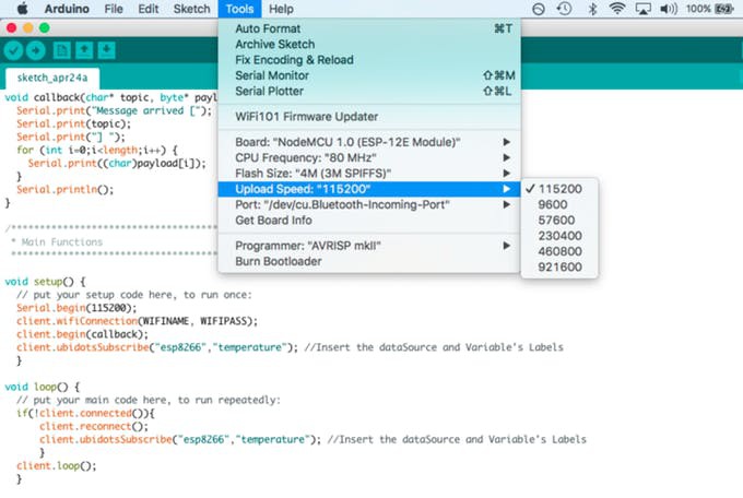
Also, to keep everything running fast and smooth - let's make sure the upload speed is optimized to 115200.
Go to Tools > Upload Speed > 115200:
![]()
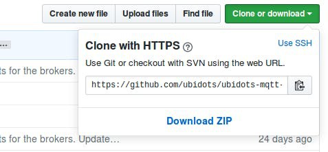
4.- Next we need to download the Ubidots MQTT ESP library from Github. To do this, open the MQTT ESP library here, download the library by clicking the green button called "Clone or download" and select "Download ZIP".
![]()
5.- Now move back to your Arduino IDE, click on Sketch -> Include Library -> Add .ZIP Library
6.- Select the .ZIP file of ubidotsMQTTESP and then “Accept” or “Choose”
If successful, you will receive this message below in the Arduino IDE confirming your library:
![]()
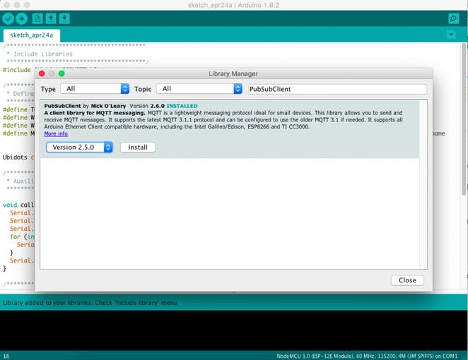
7.- Next go to Sketch/Program -> Include Library -> Library Manager and install the PubSubClient library. To simply find the correct library, search PubSubClient within the search bar.
![]()
8.- Close the Arduino IDE and open it again. The restart is required. Please do not miss this step!!
Now it is time to start coding :)
Copy the code below and paste it into the Arduino IDE.
Once you have copied the code, you will need to assign the parameters: Wi-Fi name and password, plus your individual, unique Ubidots TOKEN. If you don't know how locate your Ubidots TOKEN, please reference this article below.
CODE
/****************************************
 * Include Libraries
 ****************************************/
#include "UbidotsESPMQTT.h"
/****************************************
 * Define Constants
 ****************************************/
#define TOKEN "..." // Your Ubidots TOKEN
#define WIFINAME "..." //Your SSID
#define WIFIPASS "..." // Your Wifi Pass
#define MQTTCLIENTNAME "..." // Your MQTT Client Name, it must be unique so we recommend to choose a random ASCCI name
#define DEVICE "pir-sensor" // Assign the device label
#define VARIABLE "motion" // Assign the variable label
#define LED 2
#define SENSOR D6
uint8_t contador=0;
unsigned long estado = 0;
Ubidots client(TOKEN, MQTTCLIENTNAME);
/****************************************
 * Auxiliar Functions
 ****************************************/
void callback(char* topic, byte* payload, unsigned int length) {
  Serial.print("Message arrived [");
  Serial.print(topic);
  Serial.print("] ");
  for (int i=0;i<length;i++) {
    Serial.print((char)payload[i]);
  }
  Serial.println();
}
/****************************************
 * Main Functions
 ****************************************/
void setup() {
  // put your setup code here, to run once:
  Serial.begin(115200);
  pinMode(SENSOR, INPUT);
  pinMode(LED, OUTPUT);
  client.wifiConnection(WIFINAME, WIFIPASS);
  client.begin(callback);
  }
void loop() {
  // put your main code here, to run repeatedly:
  if (!client.connected()) {
      digitalWrite(LED, LOW);
      client.reconnect();
      digitalWrite(LED, HIGH);
  } else {
      digitalWrite(LED, HIGH);
  }

  uint8_t sensorValue = digitalRead(SENSOR);
  bool flag = false;     if(sensorValue>0){
    for(uint8_t espera=0; espera<=4; espera++){
      sensorValue = digitalRead(SENSOR);
      Serial.println(sensorValue);
      if(sensorValue==1){
      contador++;
      }
      if(contador>3){
        flag = true;
      }
      delay(500);
    }
  }
    Serial.println("sending data");
  uint8_t value;
  if(flag){
    value = 1;
    client.add(VARIABLE, value);
    client.ubidotsPublish(DEVICE);
  }else{
    value = 0;
    if(estado == 10000){
      client.add(VARIABLE, value);
      client.ubidotsPublish(DEVICE);
      estado = 0;
    }
  }
  estado++;
  client.loop();
  contador = 0;
}
Once you pasted the code and updated the WiFi parameters, you must Verify this within the Arduino IDE. To do this, in the top left corner of our Arduino IDE you will see the below icons. Choose the Check Mark icon to verify any code.
![]()
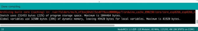
Once the code is verified, you will receive a "Done compiling" message in the Arduino IDE.
![]()
Next, your have to upload the code into your NodeMCU. To do this, choose the right-arrow icon beside the check mark icon.![]()
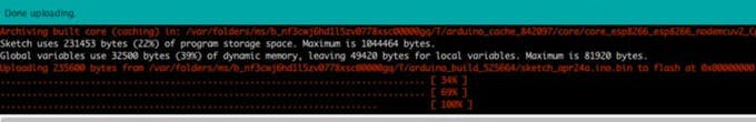
Once the code is uploaded, you will receive a "Done uploading" message in the Arduino IDE.
![]()
Now your sensor is sending the data to the Ubidots Could!Status LED
Once your code is uploaded, the onboard LED will alert you the devices connectivity.
- LED on -> Ok, device connected and sending data.
- LED blink (1 second) -> Trying to reconnect. Lost the connection. No acces to internet.
- LED off -> Device not connected
-
3Management of the data in Ubidots
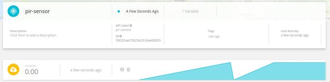
If your device is correctly connected you will see a new device created within your device section in your Ubidots application. The name of the device will be "sensor-pir", also inside the device you will see the variable created called "motion."
If you desire to change you device and variable names to a more friendly one, please reference this article
![]()
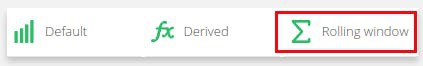
Next, to count the amount of people your device is detecting, we need to create a new derived variable to be able to manage the data and count the amount of people detected.
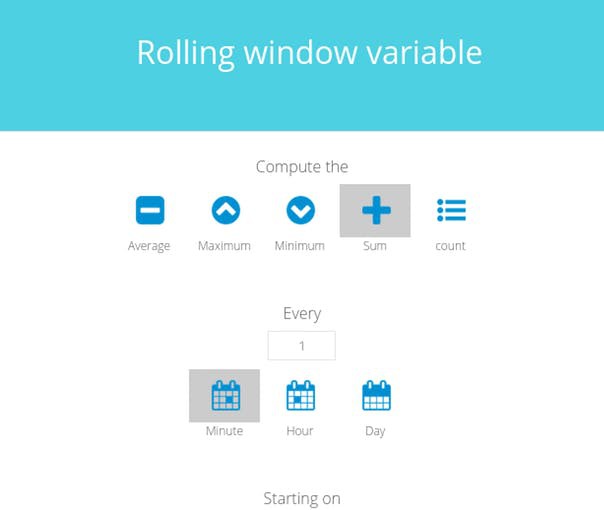
Click on "Add variable" and select "Rolling window":
![]()
Select the device called "pir-sensor" and the variable "motion" then, compute the sum every time set as you desire ( 1 minute; 1 hour; 1 day) to get the number of people detected. Press Save and assign a name for the variable.
![]()
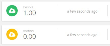
Once your variable is created, you will receive the number of people detected on that variable. Below is an illustration of the final result:
![]()
-
4Result
This project educates administrators and decision makers to the amount of people passing through a particular space and how they operate. Please note not every person will be detected due to limitations of the motion sensor. Line of sight is important for us humans and machines also struggle with this too. But we are working on it! Now it is time to create a dashboard to control and manage the variables of your own People Counter. To learn more about Ubidots widgets and events, check out these video tutorials.
Build a People Counter for $30 Using NodeMCU
This project educates administrators and decision makers to the amount of people passing through a particular space and how they operate.


Discussions
Become a Hackaday.io Member
Create an account to leave a comment. Already have an account? Log In.